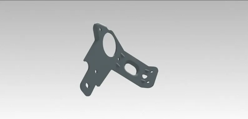
Flattening and Forming of a Sheetmetal Bracket in NX-Cad
Flattening and Forming of a Sheetmetal Bracket in NX-Cad
Objective
The main objective of this project is to design a Sheet metal Bracket and applying Flattening and Forming features by understanding different operations in Siemens NX-cad. Then Drawing sheet is to be created for the designed sheet metal Bracket.
Introduction
Sheet metal is metal formed by an industrial process into thin, flat pieces. Sheet metal is one of the fundamental forms used in metalworking, and it can be cut and bent into a variety of shapes. Countless everyday objects are fabricated from sheet metal. Sheet metal is available in flat pieces or coiled strips. The coils are formed by running a continuous sheet of metal through a roll slitter. Parts manufactured from sheet metal must maintain a uniform thickness for ideal results. There are many different metals that can be made into sheet metal, such as aluminum, brass, copper and steel.
NX, formerly known as "Unigraphics", is an advanced high-end CAD/CAM/CAE, which has been owned since 2007 by Siemens PLM Software. In 2000, Unigraphics purchased SDRC I-DEAS and began an effort to integrate aspects of both software packages into a single product which became Unigraphics NX or NX.
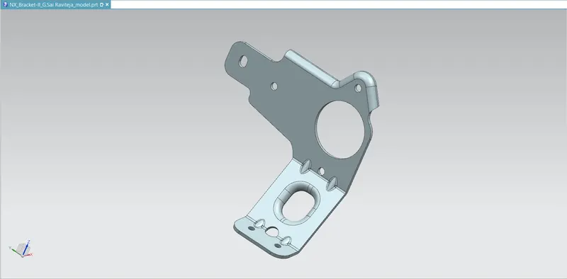
In this project Bracket was created to understand the basics of sheet metal application in Siemens NX. These Bracket has some important features like Contour flange, Normal cutout, bead and holes. Then Flattening and Forming features are applied to these Sheetmetal.
Neutral data file
A Neutral file is a formatted text file containing information about parts and assemblies created in Creo. The Creo application formats part geometry data so that other software systems can easily read it and a wide variety of applications can use it. You can create neutral files from parts and assemblies.
Part Neutral files contain information about the part geometry and the features of the part. Assembly Neutral files contain information about how the parts and subassemblies are placed in the assembly and general information about the component parts. When you create a Neutral file from an assembly, the system generates a Neutral file for each component part, and the assembly Neutral file contains a list of the individual part file names.
If the part or assembly has faceted data, the faceted data is exported to the Neutral file format.
The Neutral file contains information about parts and assemblies which is not supported by IGES. With a Neutral file, you can access this information and use it to create interfaces with other programs.
You cannot open in the earlier versions of Pro/ENGINEER parts and assemblies created in the current version of Creo. However, you can use the Neutral file format to collaboratively share data with the earlier versions of Pro/ENGINEER. See the Help module Associative Topology Bus for more information.
Part Neutral Files
Part Neutral files include the feature and geometry data for one part only. Each part Neutral file contains one-part entity, one or more feature entities, and as many surface and edge entities as are needed to describe the part geometry. A part Neutral file can also contain other entities such as associated text files and mass properties.
Neutral files follow the naming convention .neu.#, where is the name of the part or assembly the system uses to generate the data file and # is the version or index of the Neutral file created.
To create a Neutral file, you must first retrieve the part or assembly.
Neutral file exchange uses an intermediary neutral format to translate data between CAD systems. This method starts from a pre-processor embedded in the original CAD system, which generates the neutral file from the originating CAD format.
List of various neutral Data files:
- STEP (File Extension: *.STEP, *.STP)
- IGES (File Extension: *.IGS, *.IGES)
- PARASOLID (File Extension: *.X_T)
- ACIS (File Extension: *.SAT)
- QIF (File Extension: *.QIF)
Design Methodology
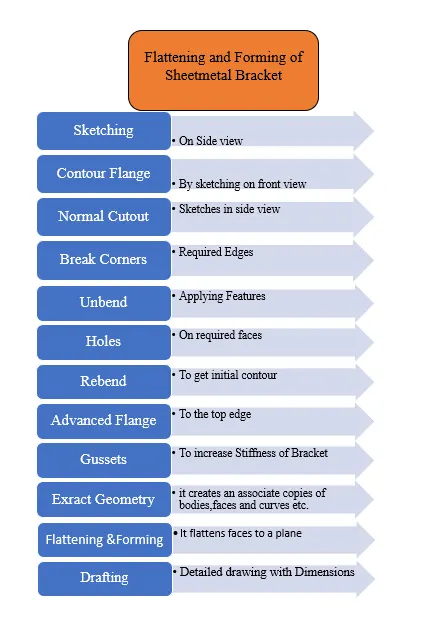
Description
List of Features used for designing the Bracket:
Sketch - It is a basic and initial operation for creating any kind of sheet metal components.
Contour Flange - It creates a base feature by extruding a sketch along a vector or adds material by sweeping a sketch along an edge or chain of edges.
Normal cutout - It cuts the model perpendicular to the sketch.
Break corner - It Rounds a sharp corner at edges
Unbend - It flattens a bend and material adjacent to the bend.
Hole - It creates a whole on basis of circle created.
Gusset - It is a stiffness part which helps to increase the stiffness of the Sheetmetal part.
Advanced Flange - It adds a flange along an edge using a bend angle or reference face. It results in edge and reference face to be curved.
Re-bend - It restores a bend.
Flat pattern - It creates a flattened pattern from the formed sheet metal part.
Trim Sheet - It trims of a portion of sheet body.
Thicken Surface - It thickens the surface of body on basis of required dimensions.
Flattening and Forming - It flattens faces to a plane and reapplies the required modifications to other objects.
Forming and Reuse - It Reuses the flattening procedure of an existing feature to wrap or unwrap additional selected objects.
Procedure for designing Bracket:
- At first required plane is selected for sketching right side view with required geometry.
- Then another plane for sketching front view is selected by applying some dimensions.
- Contour flange is applied to the sketch drawn on right view.
- Normal cutout is applied by selecting the sketch drawn on front view as reference for removing the material at required positions.
- The sharp corners are removed at required edges by applying break corner.
- Then by selecting on face as reference whole is selected for unbent for adding more features like dimples, holes etc.
- Points are added at required positions for applying holes.
- Then Sheetmetal bracket is re-bent.
- All other sharp corners are removed by applying break corner.
- Then Advanced flange is added to the top v - shaped portion by applying required length.
- Again, unbent the whole part for applying required features and re-bent it.
- Then for center portion ellipse is drawn with required dimensions for applying normal cutout.
- Advanced flange is applied by selecting the edge of these elliptical normal cutout with required length.
- Finally, gussets were added for increasing stiffness of Sheetmetal bracket on either side of elliptical cutout on the bent surface.
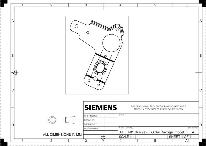
- At last these Sheetmetal is converted into blank sheet by applying flat pattern.
- Then these designed Sheetmetal is converted into neutral data file.
- By using these neutral data file two cases were done by using Flattening and Forming.
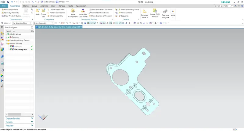
- In first case solid body was Flattened and thickened by using commands flattening and by applying dimensions to thicken surface.
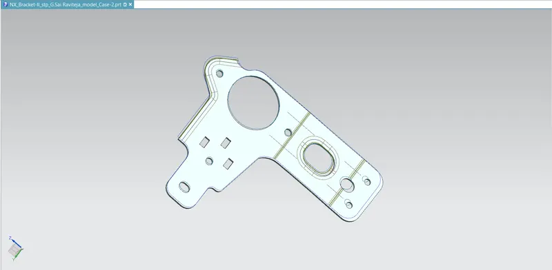
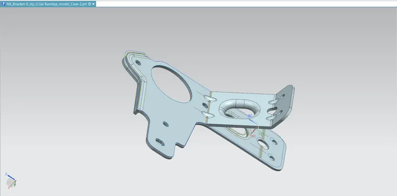
- In second face flattened surface were extracted and added required sketches for applying cutouts with Forming.
- Then these flattened surfaces are thickened again by using thicken feature.
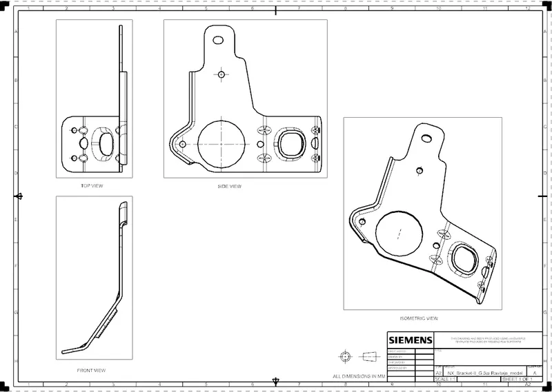
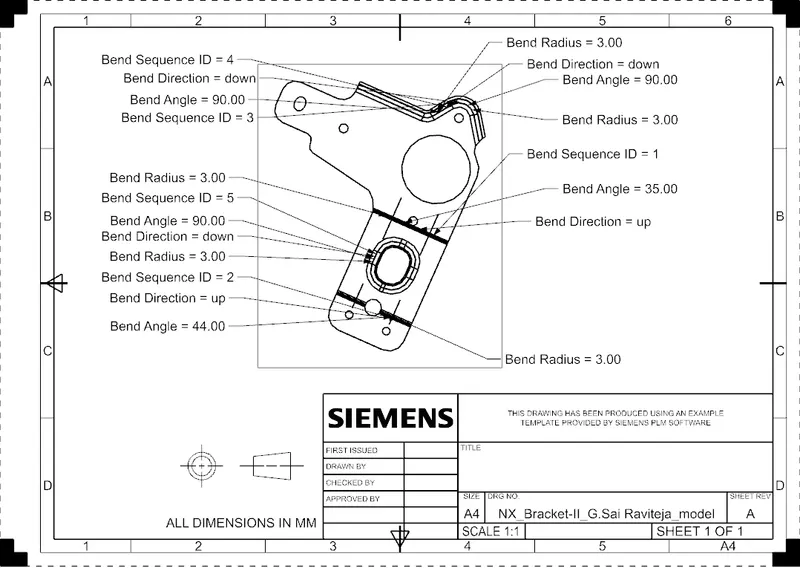
- Then on basis of base view by selecting flat pattern drawings are created on draft file.
Different views of Bracket
Isometric view:
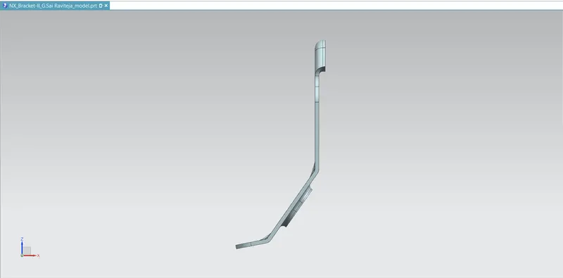
Front view:
Top view:
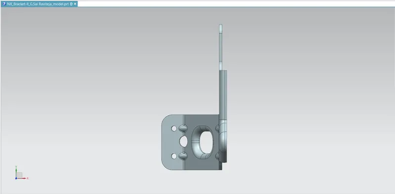
Right Side view:
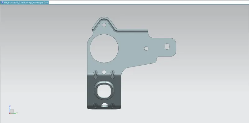
Bottom view:
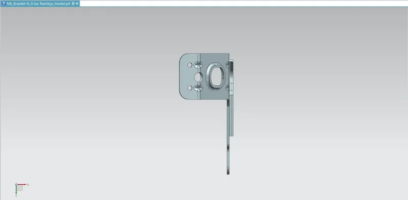
CASE 1:
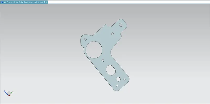
CASE 2:
Drawing sheet of Bracket:
Flat Pattern:
Sheet with dimensions:
Conclusion
Thus, the designing of Bracket by using NX-Cad applications has been created and drafted.