Advanced Sheet Metal Design Using NX Cad Challenge_6_Bracket
SHEET METAL BRACKET IN NX CAD
Objective -
Design a sheet metal bracket using a 2d drawing in NX Cad sheet metal application.
Introduction -
NX Sheet Metal Design provides the design professional with a complete set of tools to efficiently create and manage sheet metal parts based on the knowledge of material properties and manufacturing processes. NX Sheet Metal Design tools incorporate material and bending information, enabling the model to represent both the formed component and flattened blank shapes.
Design methodology -
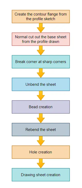
Description -
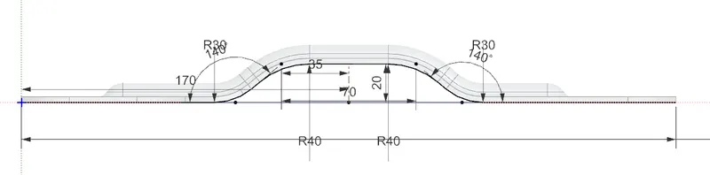
Sketch :
Create a sketch according to the drawing for contour flange operation.
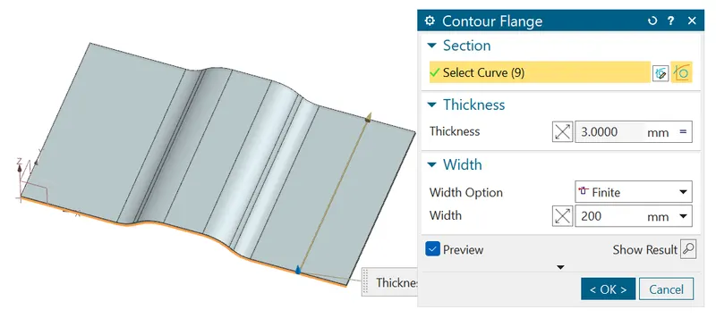
Contour Flange :
Create a flange using contour flange tool of 200mm width and 3mm thgickness.
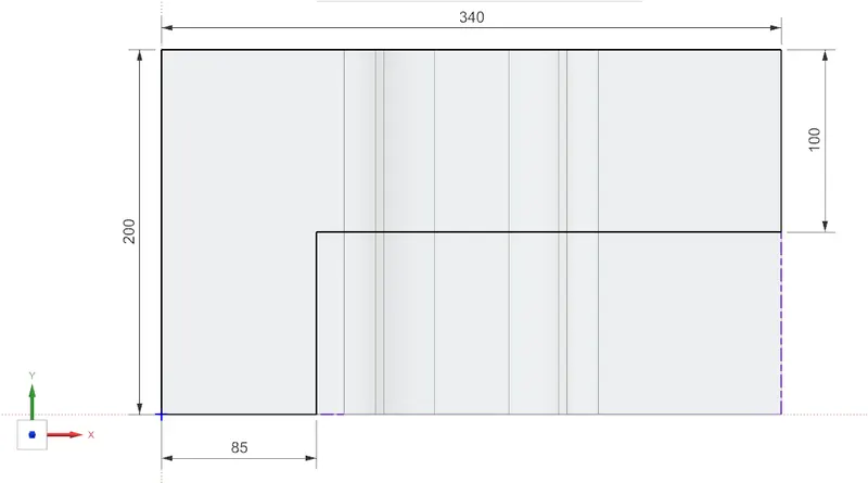
Sketch for cutout :
Create a sketch of certain dimension according to drawing to remove the unwanted part.
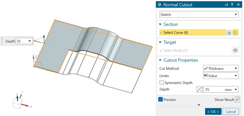
Normal Cutout :
Using the privious created sketch cut the sheet with proper direction, that is required.
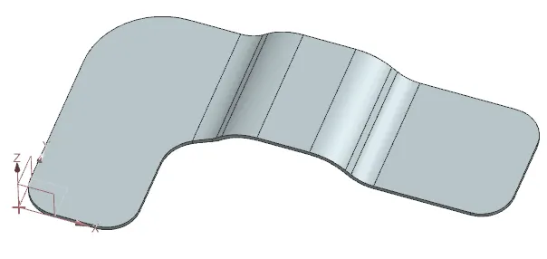
Break Corner :
Now break all the corner with a proper fillet dimensions.
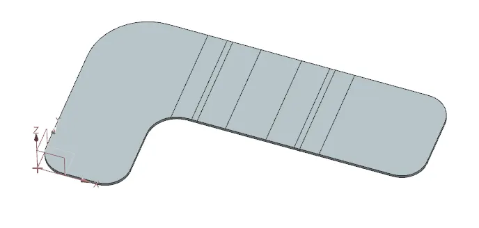
Unbend :
Now Unbend the hole sheet.
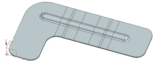
Bead :
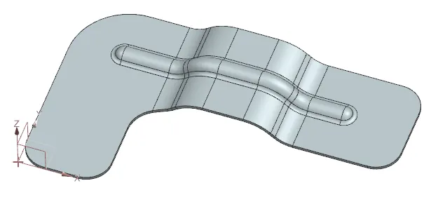
Create a sketch with proper dimension and use 'Bead' tool to make dimple on the sheet.
Rebend :
Now rebend the hole sheet with proper order.
Hole :
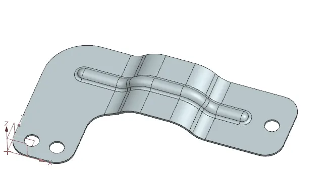
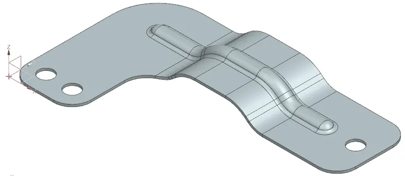
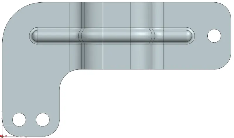
Create 3 hole of 20mm dia on the sheet with proper position.
Flat Pattern :
At the end flat the hole sheet to make the draft sheet properly.
Model Views -
Isometric View :
Front View :

Top View :
Left Side View :

Right Side View :

Bottom view :
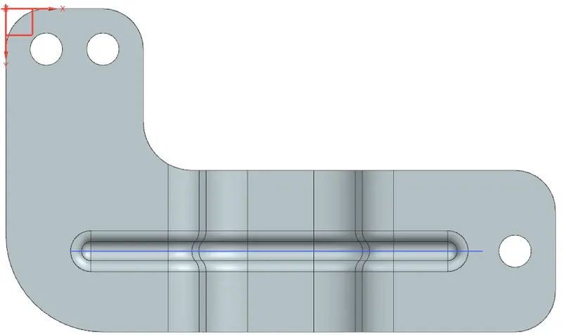
Draft Sheet :
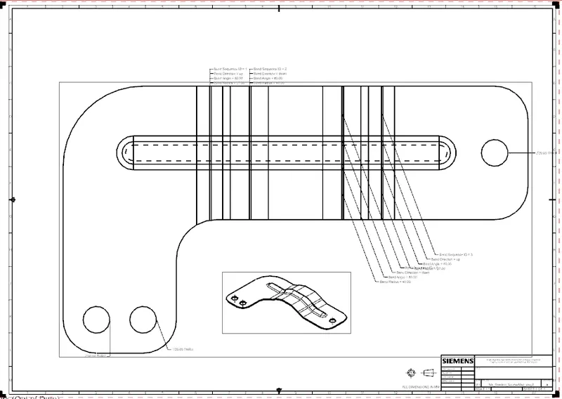
Conclusion -
Bracket is created is using advanced sheet metal tools in NX CAD.