Advanced Sheet Metal Design Using NX Cad Challenge_6_Bracket
Title of the project:- Advanced Sheet Metal Design Using NX Cad Challenge_6_Bracket
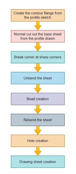
- Open new sheet metal part in NX cad
- Create contour flange using sketch with given parameters
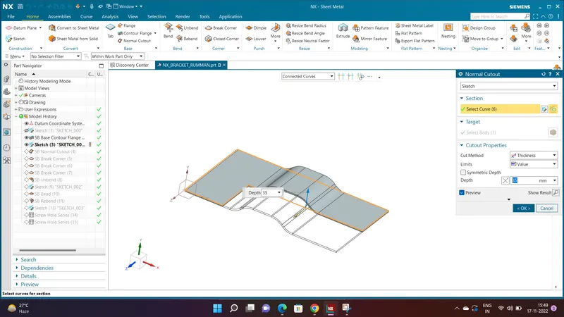
- Cut the body using normal using given dimensions
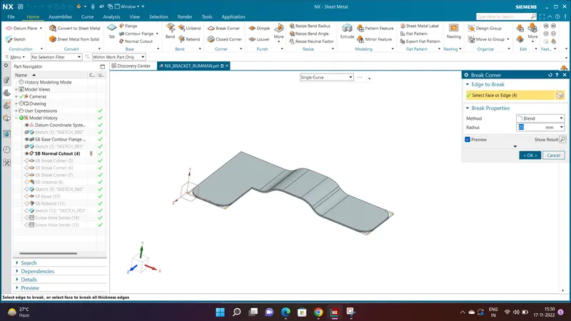
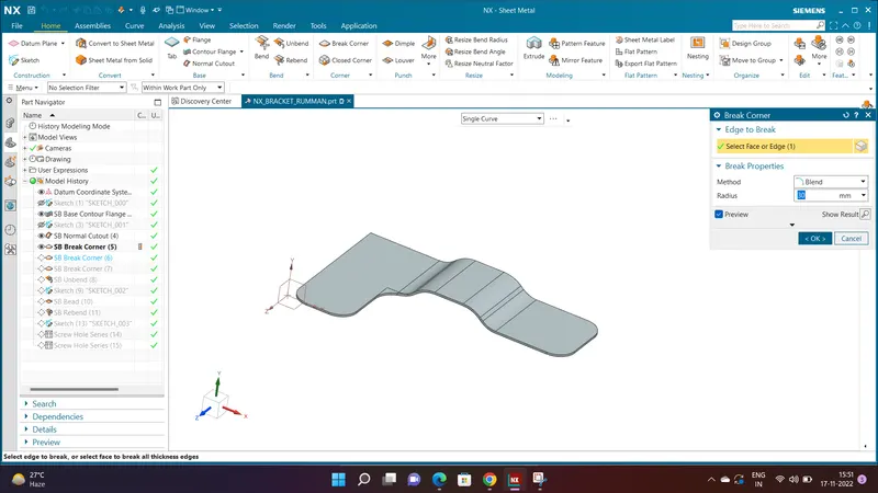
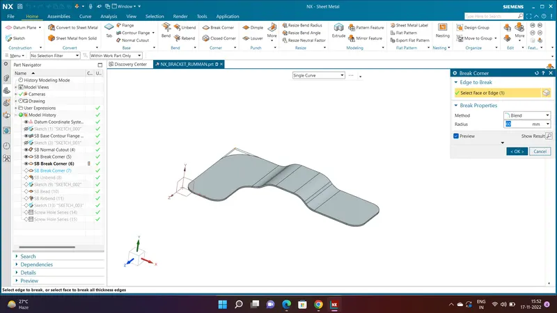
- Give some break corners with required dimensions
- Unbend the model and create bead with using line sketch
- Create some holes as per requirements
- Rebend the model
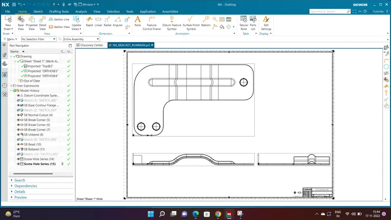
- If required create the drawing sheet using draft tool for understanding to customer
- Hence the model is ready
Description :
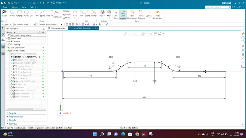
Create the base sketch from reference to the given bracket sketch. Create the sketch profile as shown in the below picture
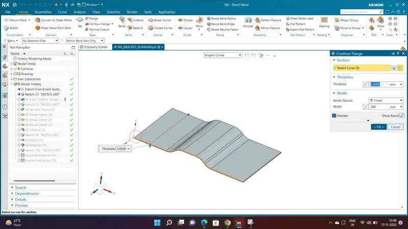
By using contour flange, create the base to a length of 200 mm
Create a sketch on top plane as shown in figure
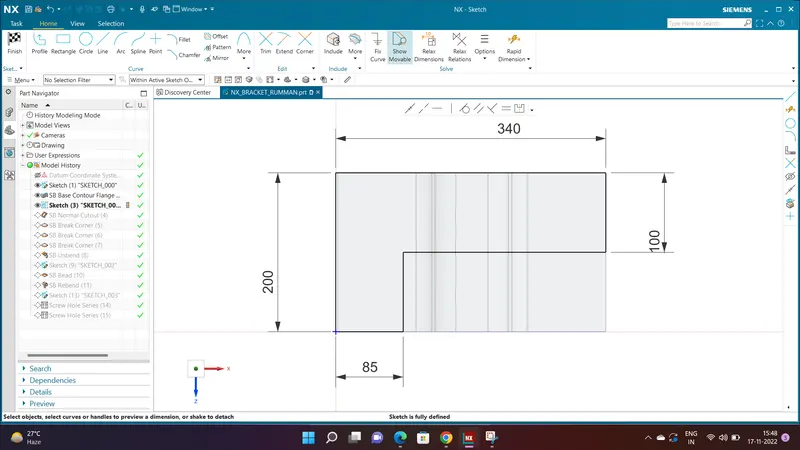
Create a normal cutout:-
Smoothen the sharp corners using break corner option with a radius values of 25 mm
Break corner using radius 30 mm
Break corner using 60 mm radius
Unbend the bracket
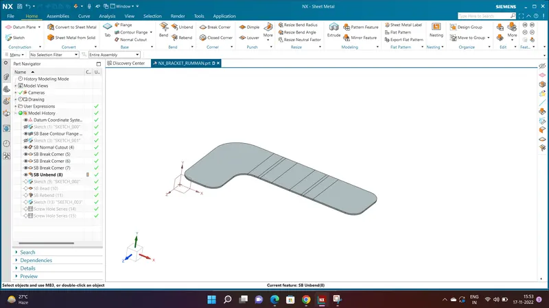
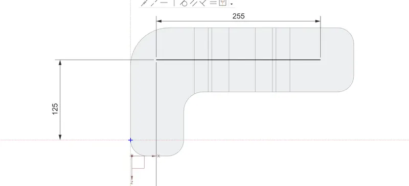
Create the sketch for bead:-
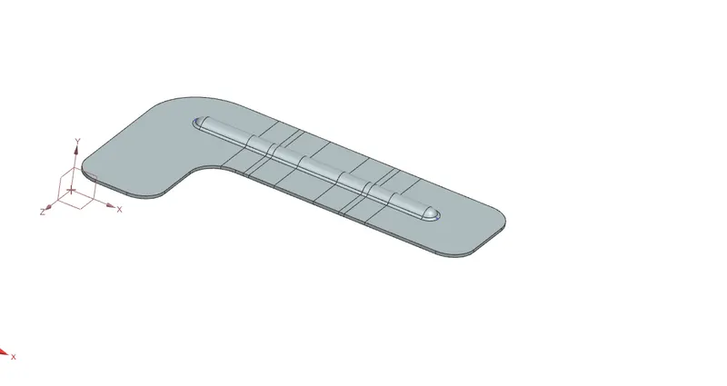
Rebend the bracket
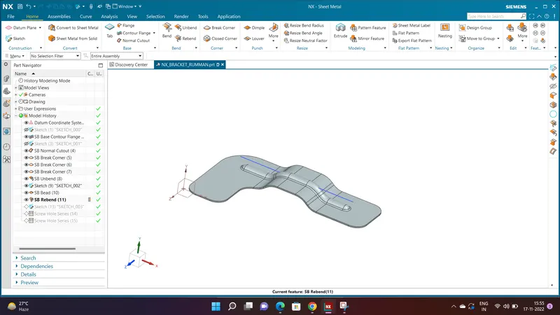
Create a points on top view to locate the holes
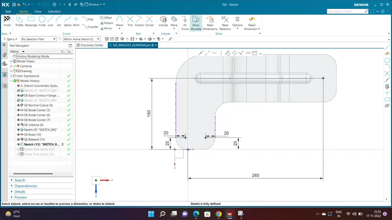
Create the holes using hole command
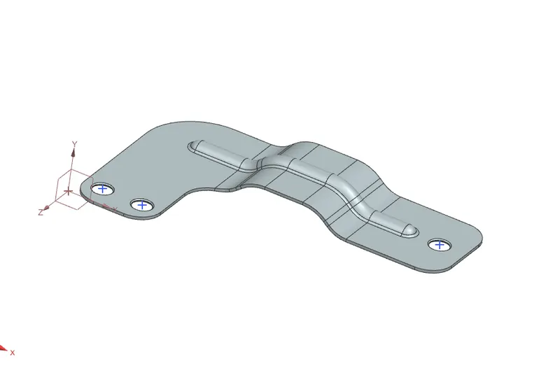
Views :
FRONT VIEW:-
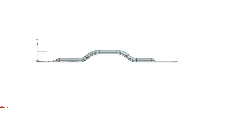
LEFT VIEW:-
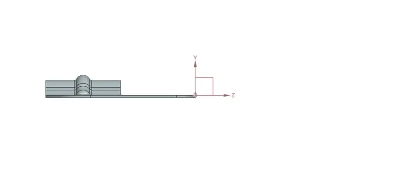
RIGHT VIEW:-
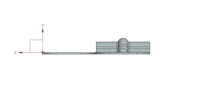
TOP VIEW:-
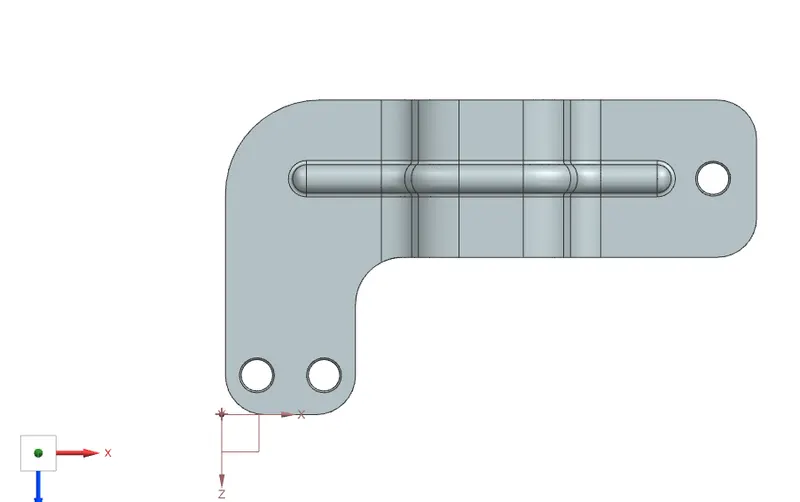
BOTTOM VIEW:-
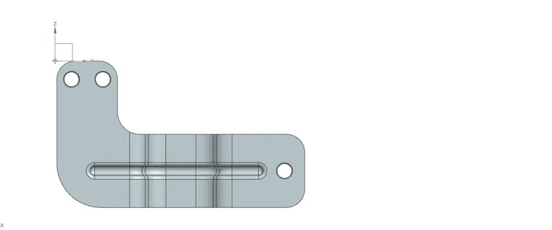
ISOMETRIC VIEW:-
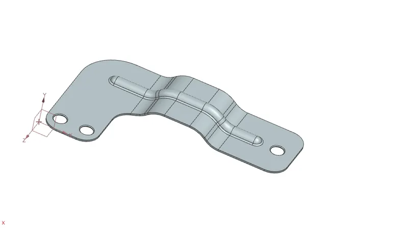
DRAWING SHEET:-
Conclusion :
Bracket is created is using advanced sheet metal tools in NX CAD.