Advanced Sheet Metal Design Using NX Cad Challenge_6_Bracket
Advanced Sheet Metal Design Using NX Cad Challenge_6_Bracket
Objective
Write a detailed report on Sheet Metal Component with good explanation on Sheet Metal modelling tools applied throughout the modelling. Also attach the Final model Images (Min. 4 images) of Sheet Metal Bracket.
Introduction
Sheet Metal Fabrication is the process of forming parts from a metal sheet by punching, cutting, stamping, and bending. Parts are formed from a single sheet of metal, designs must maintain a uniform thickness. Parts used for low volume prototypes, and high volume production runs are most cost-effective due to large initial setup and material costs. Sheet metal parts are known for their durability, which makes them great for end use applications (e.g. chassis). They are used in different machineries, automobiles, and aerospace sectors.
Sheet metal components can be created in NX under sheet metal module. From a sketch it can create both simple and complex components using different features such as Tab, Bend, Flange, Hem, Jog, Bead, Dimple, Cutout, Louver, Punch, Unbend etc. Then it is converted in flat pattern for manufacturing purpose. In this project, A Bracket is created in NX using few of the previously mentioned operations.
Design methodology
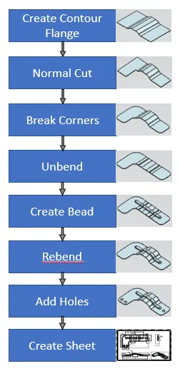
Description
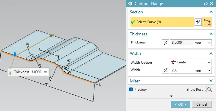
- Contour Flange- Creates a base feature by extruding a sketch along a vector, or adds material by sweeping a sketch along an edge or chain of edges.
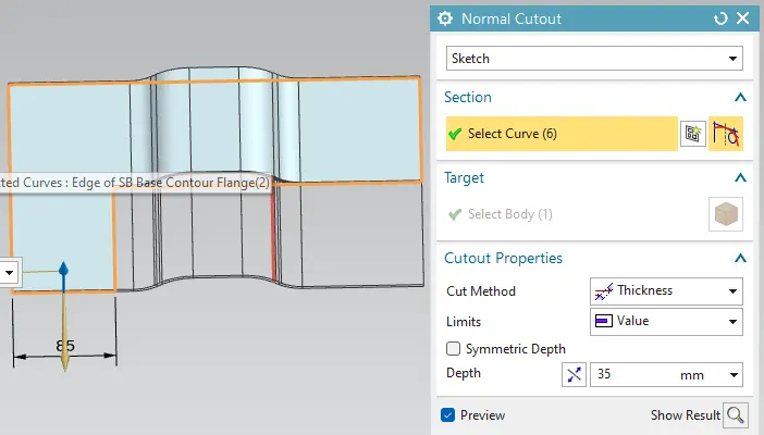
- Normal Cutout-Cuts material by projecting a sketch onto the model and then cutting perpendicular to the faces intersected by the projection.
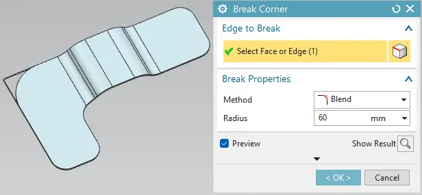
- Break Corner- Rounds or chamfers a sharp corner of a tab or flange
- Unbend- Flattens a bend and the material adjacent to the bend.
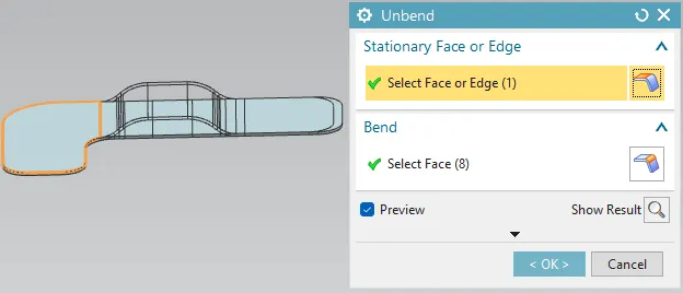
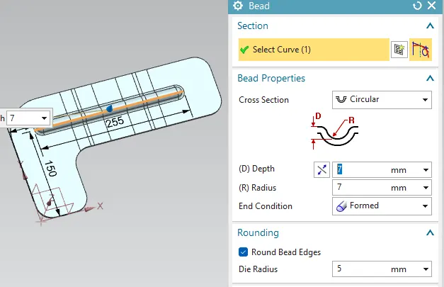
- Bead- Lifts material along the contour of a sketch that simulates a stamping tool
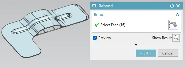
- Rebend- Restores an unbend feature to its previous bent state, along with any features added after the unbend feature.
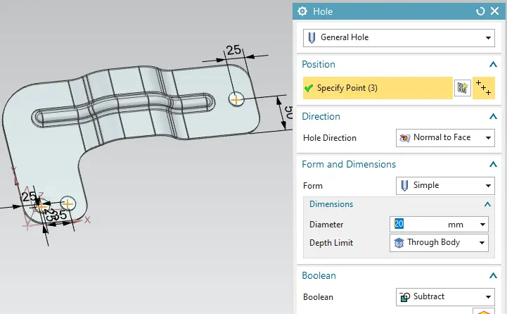
- Hole- Adds a hole to one or more solid bodies in a part or assembly with options for counterbored, countersunk, and threaded.
- Flat pattern- Creates a flat pattern from the formed sheet metal part. This feature is generally used in the end after performing all operations.
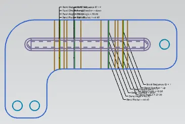
OUTPUT
Feature Tree
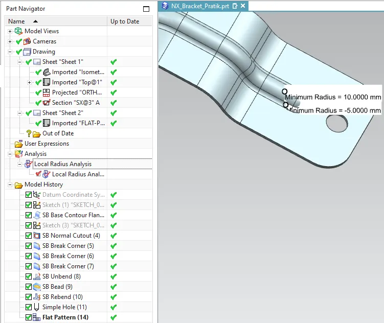
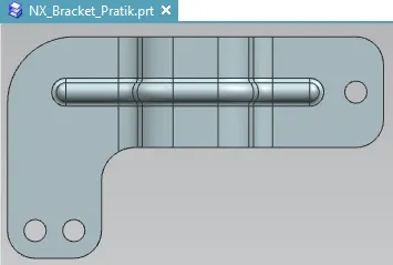
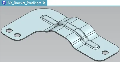
3D Model Views
|
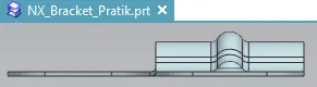
FRONT
|
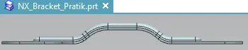
SIDE
|
|
TOP
|
ISOMETRIC
|
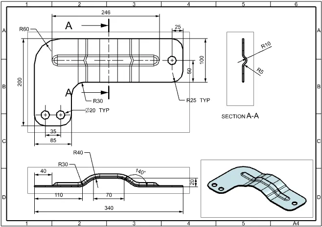
DRAWING SHEET
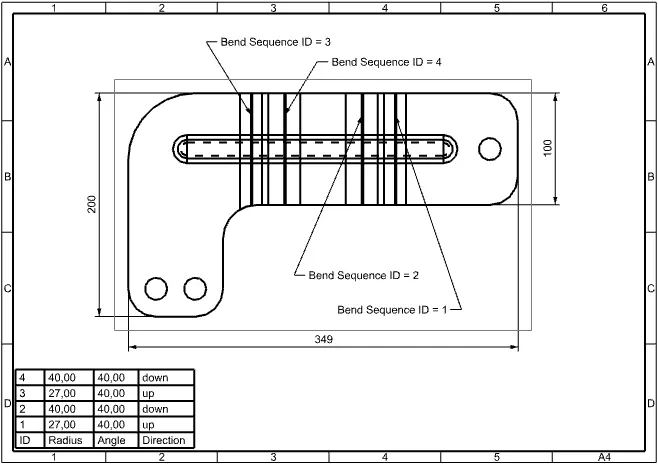
Conclusion
A Sheet metal component Bracket is created as per the given data in NX by using features such as Contour Flange, Bead, Hole, Normal cutout, Unbend, Rebend etc to create component. And flat pattern is created in the end and created Drawing sheet.