Advanced Sheet Metal Design Using NX Cad Challenge_6_Bracket
Design of Bracket Component in NX Sheet Metal Application
- Objective - To design and model the sheet metal bracket from a 2D sketch in sheetmetal workbench in NX CAD sheet metal application.
- Sheet Metal is metal formed by an industrial process into thin, flat pieces OR Sheetmetal is a comprehensive cold working process for metal sheets usually below 6mm, including shearing, punching/cutting/folding, riveting, splicing, etc.
- Sheetmetal is one of the fundamental forms used in metalworking and it can be cut and bent into a variety of shapes. Countless everyday objects are fabricated from sheetmetal. Thickness can vary significantly; extremely thin sheets are considered foil or leaf, and pieces thicker than 6mm are considered plate steel or structured steel.
- Sheetmetal is available in flat pieces or coiled strips. The coils are formed by running a continuous sheet of metal through a roll slitter.
- Design Methodology -
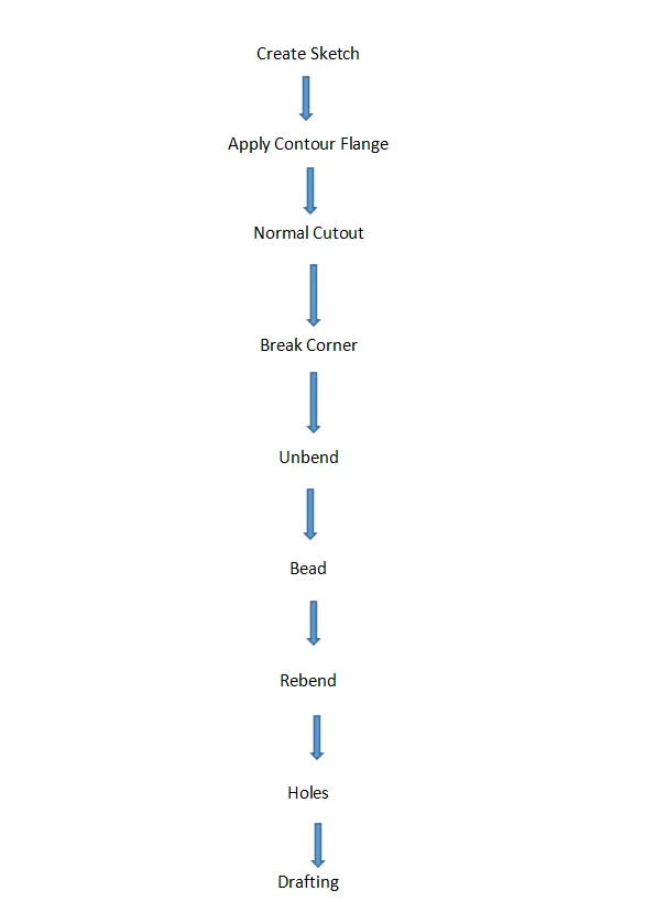
- Description - Features used for modeling bracket are contour flange, normal cutout, break corner, bead to lift material along the contour of the sketch that simulates a stamping tool, Bend to bend the material, Flange to create flanges, Unbend to unbend the material, Holes for adding holes, dimple to create deformation on the sheet metal and Rebend.
- Features used in creating Designing Bracket -
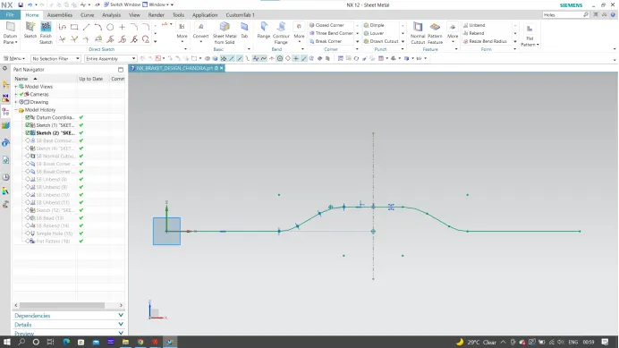
- Creating 2D sketch - 2D Sketch is created on XY, XZ, or YZ plane. With the help of a 2D sketch, we create 3D features.
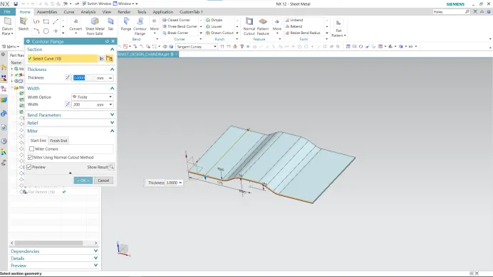
- Contour Flange - Use the contour Flange command and select the sketch, as shown above, and determine the thickness as 3mm for the flange.
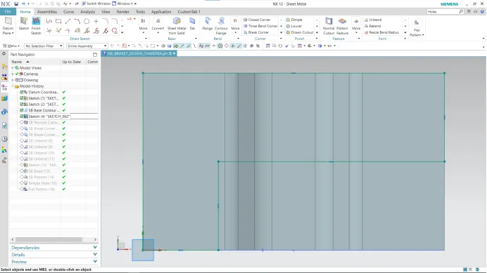
- Normal Cutout - The unbend feature is used and the sketch is created on the face of the hem flange in the flat state. Two rectangles are created as per the requirement for the hinge barrels on both sides. Then the normal cut operation is carried out.
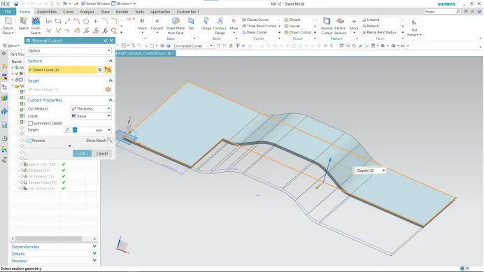
- Break Corner - This feature breaks the sharp edges in the corners and makes it round or adds chamfer. It is like the fillet feature in some other CAD software.
Corner Radius - 25 mm
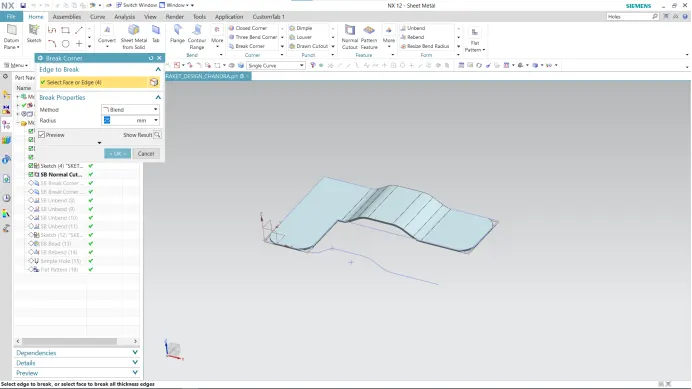
Corner Radius - 30 mm
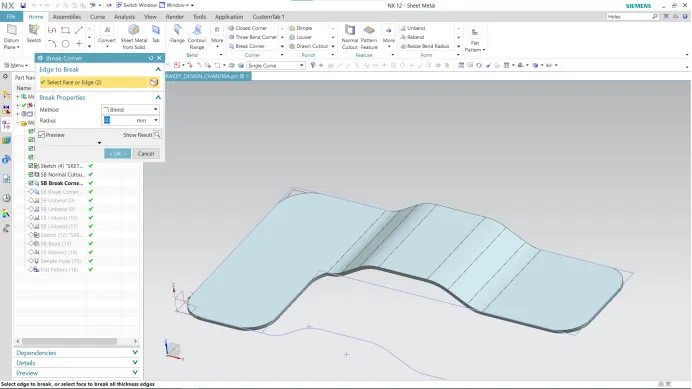
Corner Radius - 60 mm
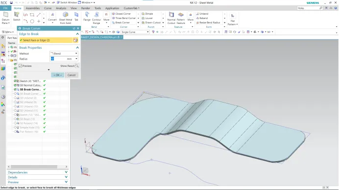
- Unbend - This command is used to unbend the sheet metal. The punching operation can be performed only by unbending the sheet metal.
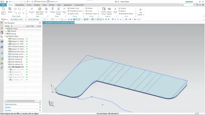
- Bead - The bead is like a raised rib in the sheetmetal panel. It requires that you have at least one sheet metal panel in the active part as well as an open or closed-loop sketch.
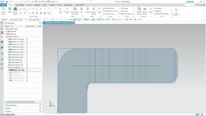
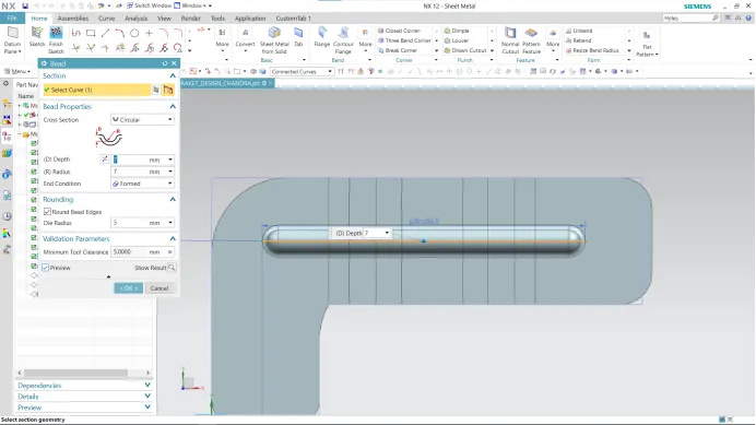
- Rebend - Following the normal cutout feature, Rebend is used to get the expected output as shown in the image below. After finishing all these operations, then the sheet metal part should to Rebend to check the DFM (Design for manufacturing) process.
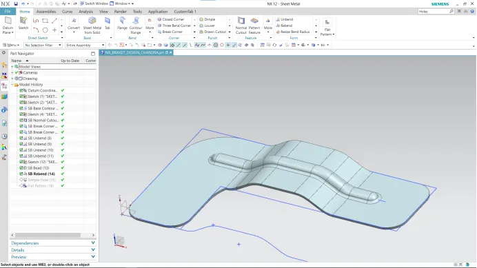
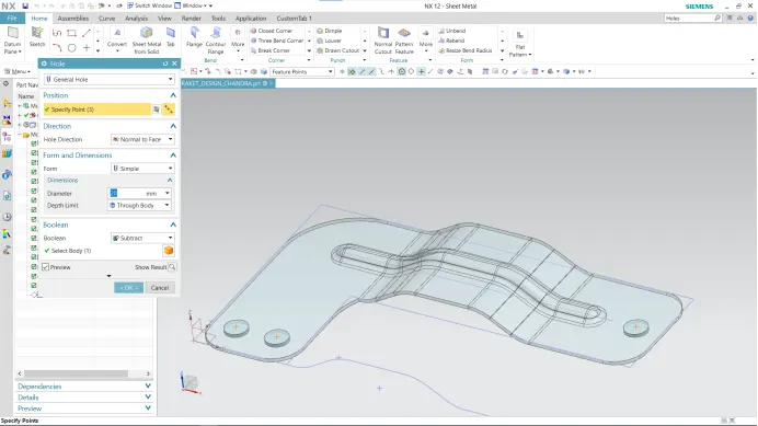
- Holes - Holes are added to provide alignment to enclosure. NX provides whole feature has options like general type, counterbore, countersink, etc. Position, Diameter and depth are important inputs to apply holes to a body.
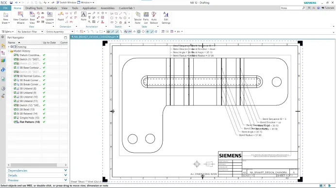
- Drafting -
- Front View -
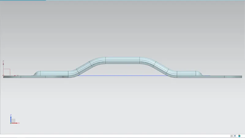
- Side View -
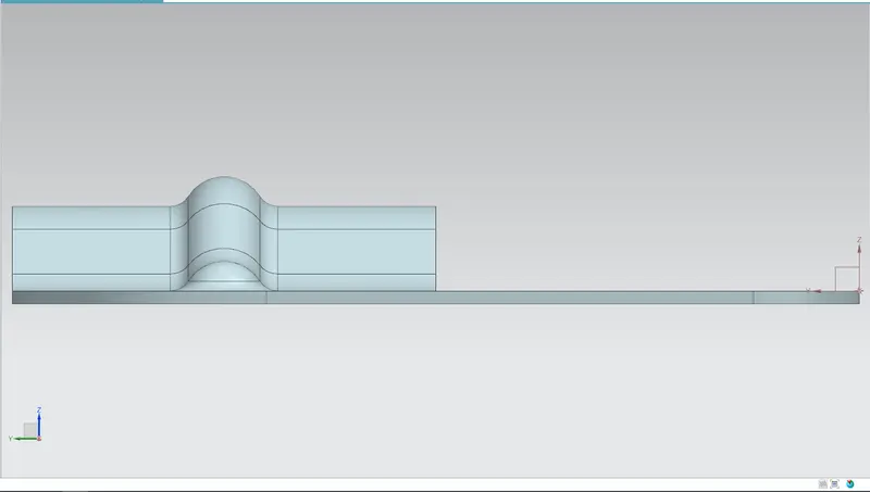
- Top View -
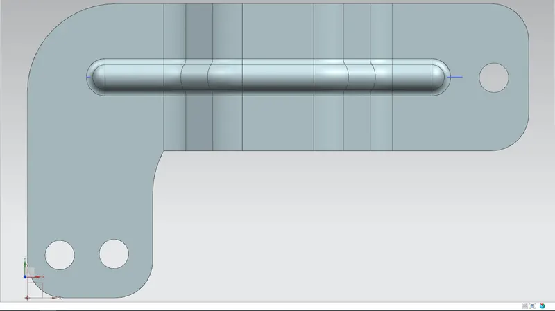
- Bottom View -
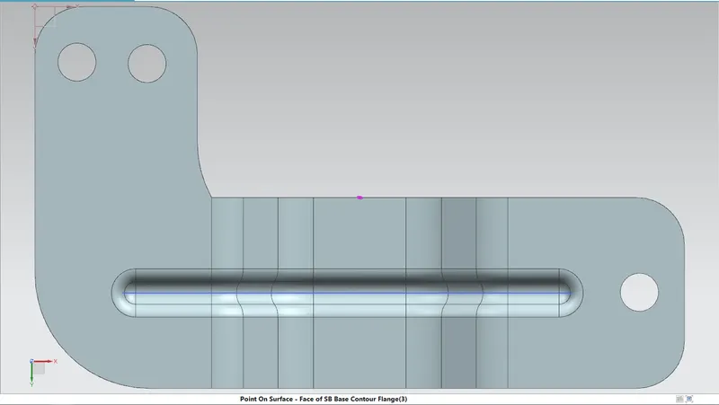
- Isometric View -
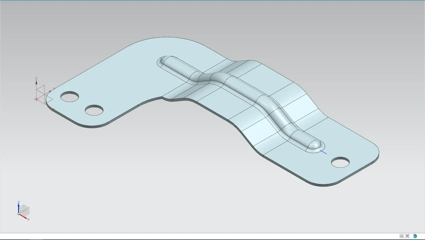
- Conclusion - The sheet metal recommended workflow to create Bracket components or angles is successfully completed in NX CAD.