Advanced Sheet Metal Design Using NX Cad Challenge_6_Bracket
Bracket Creation
Objective
To create a bracket using NX CAD as per the design requirements and write a detailed report on Sheet Metal Component with good explanation on Sheet Metal modelling tools applied throughout the modelling.
Introduction
The challenge is to create a bracket using NX cad and the design parameters provided. A bracket is a sheet metal component that is used across most industries for the purpose of fastening and fixtures. Each sheet metal bracket serves a different purpose for mounting a component or to be able to mate a surface properly. There are many types of brackets that is used in the industry such as L-Shaped Brackets, Z-Shaped Brackets, U-Shaped Brackets, Gusset Brackets etc. Based on the application of these brackets, they are to be designed accordingly to provide the best fit and fastening capabilities. In this challenege, we are creating an L Shaped Bracket with some custom features like a bend in the surface and a bead to provide extra strength.
Design Methodology
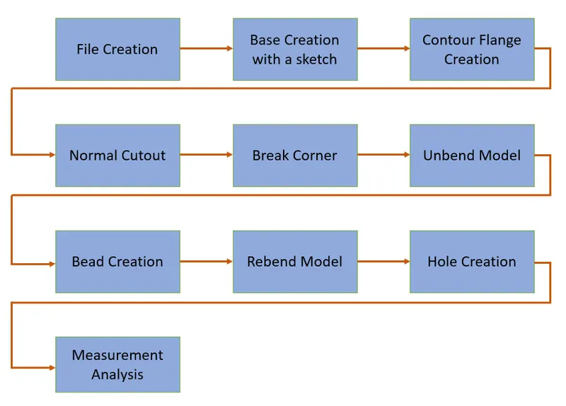
Description
The commands that were used for the creation of this model is given below:
1. Contour Flange: This command is used to create a base by using a sketch. This can be used to create slightly more complex or bent surfaces such as base body in this challenge.
2. Normal Cutout: It is used to make a cutout in the surface of the model based on a sketch and normal to the surface.
3. Break Corner: It is used to smoothen out the sharp edges in the model to make it more manufacturable and avoid the stress concentration at these corners.
4. Unbend: This command is used to remove the bends in model and thus turning the model into a flat surface for the prupose of adding additional features across multiple faces of the model.
5. Bead: The bead command is used to provide a bead feature on the surface and in turn strengthing the surface in real life application.
6. Rebend: The rebend command is used to counteract the unbend command after the desired features have been added and to bring the model back to its intended original shape.
7. Hole: This command, as the name suggests, was used for the creation of holes on the surface of the model.
8. Measure Simple Distance: This command is used to digitally measure the distance between 2 edges or surfaces.
9. Measure Local Radii: Like the previous command, this is used to measure the local radius at the chosen point on the model.
Views of the Model
The images provided below show the model in various perspectives:
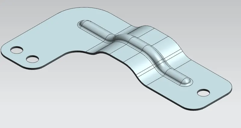
Isometric View
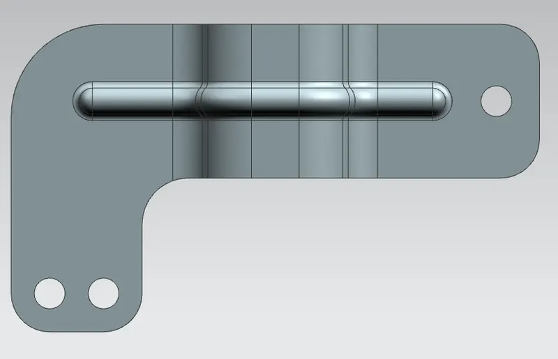
Top View
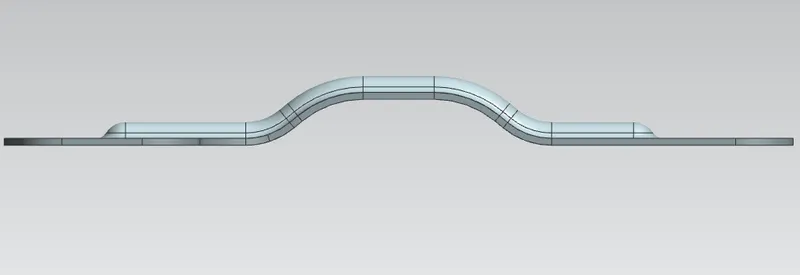
Front View
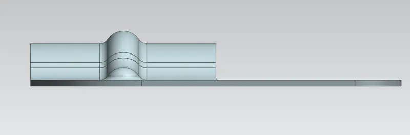
Side View
Drafting
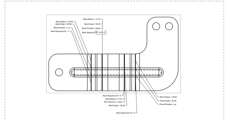
The flat pattern of this model was exported into the drafting application and a drawing/draft of the model was created. This is seen in the image below
Conclusion:
The model was created as per the design parameters provided and a draft of the model was made.