Advanced Sheet Metal Design Using NX Cad Challenge_6_Bracket
DESIGNING OF BRACKET
OBJECTIVE: The main objective of this project is to design bracket in sheet metal using NX CAD.
SOFTWARE USED: Siemens NX 11.0
FEATURES USED IN DESIGNING:
The bracket design starts with the sketch as per the given dimensions.
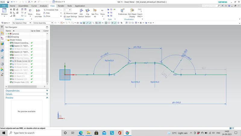
contour flange:This command is used to create a base feature by extruding or sweeping the sketch along a direction.
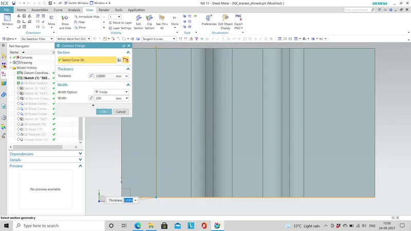
Normal cutout:It is used to cut the material which projects on the sketch and we can reverse the direction to remove the material.
Break corner: The break corner is used to round the sharp edge of tab or flange.
Unbend:It is used to flatten the bend and the parts adjacent to the bend
Bead: The bead command is used to lift an area with refernce to the sketch drawn as per the given die radius.
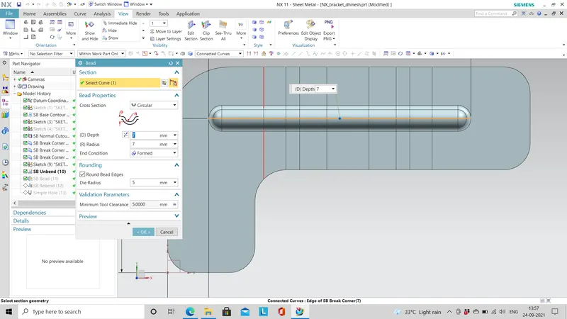
Rebend:It is used to restore the unbended material to its previous state along with the features created in the unbended state.
Hole: This option is used to add hole on one or more solid body with point as center point of the hole.
DESIGN APPROACH:
Open new model
`darr`
select a plane
`darr`
draw sketch
`darr`
use contour flange for extruding
`darr`
create a sketch for normal cutout
`darr`
use normal cutout feature
`darr`
unbend
`darr`
sketch for bead
`darr`
bead feature
`darr`
break corner
`darr`
hole creation
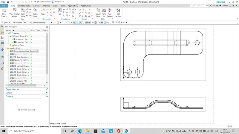
The model is created and drawing sheet is prepared for this model.
VARIOUS ORIENTATION OF MODEL:
TOP VIEW:
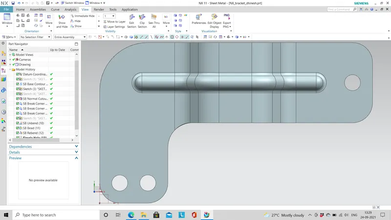
FRONT VIEW:
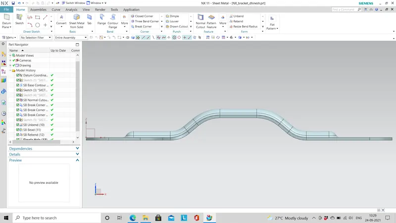
SIDE VIEW:
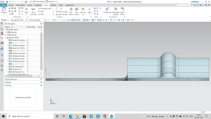
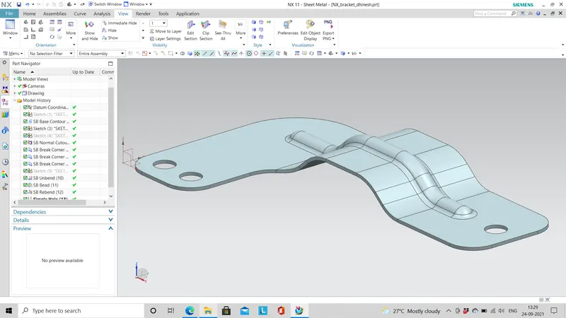
TRIMETRIC VIEW:
DRAWING SHEET IMAGE:
CONCLUSION:
- The modeling of bracket using NX is drawn and the corresponding images are attached successfully.
- Report on the project is submitted successfully. The NX model assembly file is attached below.