Advanced Sheet Metal Design Using NX Cad Challenge_6_Bracket
TITLE: Bracket designing in NX CAD.
OBJECTIVE: To create metal bracket from the given 2D drawing.
INTRODUCTION: For creating bracket from 2D drawing i have used various tools in NX CAD.
DESIGN METHODOLogy:
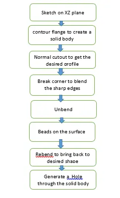
DESCRIPTION:
STEP 1:
CONTOUR FLANGE: It is created by extending the sketch on its representative axis with thickness as required from the base.
STEP 2:
Create a sketch that has to be cutout from the profile with normal cutout.
NORMAL CUTOUT: It is used to remove the material from the base.
STEP 3:
BREAK CORNER: It is used to make the corners blemd with given radius in order to make corners smooth.
STEP 4:
UNBEND: It is used for unbending corners of the body.
STEP 5:
BEAD: It is used to lift the material along the contour of the sketch.
STEP 6:
REBEND: It is used to restore the model to its bended state.
STEP 7:
HOLE: It is used to create the holes on the model.
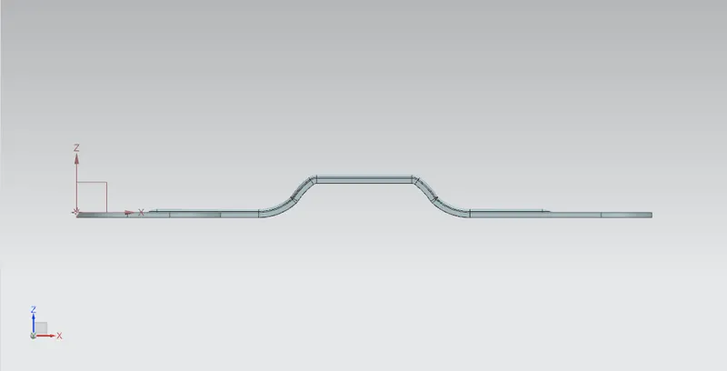
FRONT VIEW:
TOP VIEW: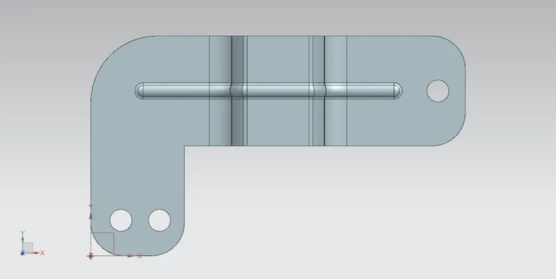
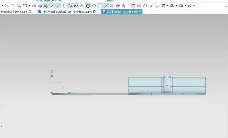
SIDE VIEW:
ISOMETRIC VIEW: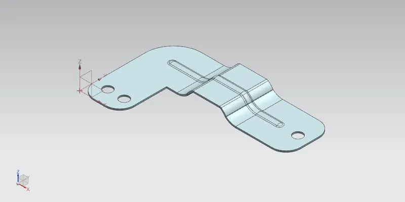
DRAWING SHEET:
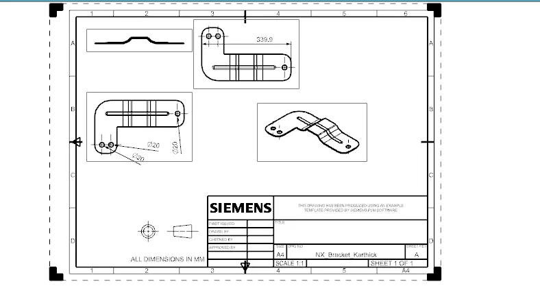
CONCLUSION:
Thus we have successfully designed metal bracket using 2D drawing using NX CAD.