Advanced Sheet Metal Design Using NX Cad Challenge_6_Bracket
SHEET METAL DESIGN OF BRACKET
OBJECTIVES
- To design bracket in NX sheet metal.
- To draft the box assembly in A3 sheet.
INTRODUCTION
In this design the bracket is designed by grasping the technical details from the 2D drawing sheet. It is designed using Siemens NX12.
SHEET METAL HOLE DESIGN GUIDELINES
Minimum Distance from Extruded Hole to Part Edge
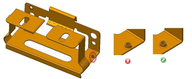
Extruding metal is one of the most extreme pressure applications in press working and generates lot of friction and heat. If an extruded hole is too close to the part edge, it can lead to deformation or tearing of the metal. It is recommended that the minimum distance between the extruded holes to part edge should be at least three times the thickness of sheet.
Minimum Distance Between Extruded Holes
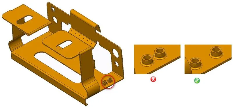
Certain distance should be maintained between two extruded holes in sheet metal designs. If extruded holes are too close it can lead to metal deformation. It is recommended that the minimum distance between two extruded holes should be six times the thickness of sheet metal.
Minimum Hole Diameter
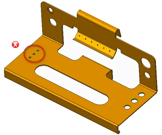
The diameter of the hole in sheet metal part should not be very small, small holes are created by piercing operation and for manufacture small holes, small sizes punches are required. Small hole size in sheet metal requires smaller size punching tool which may leads to break during the operation. It is recommended that the diameter of the hole should be equal or more than the thickness of the sheet metal.
Minimum Distance from Extruded Hole to Bend
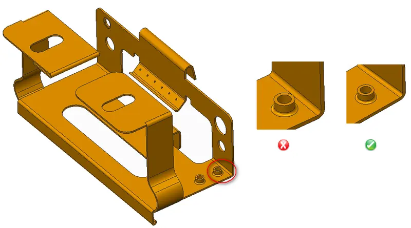
A certain distance must be maintained between extruded hole to bend to avoid metal deformation and fracturing. It is recommended that the minimum distance between extruded hole and bend should be three times the thickness of sheet metal plus bend radius.
PROCESS FLOW
2D DRAWING – studying the drawing and understanding the features and its dimensions.
CONTOUR FLANGE – sketch the contour flange as inferred from the drawing (thickness=3mm, width=200mm).
NORMAL CUTOUT – removing a rectangular section from the flange created.
BREAK CORNER – 25mm, 30mm, 60mm were used.
UNBEND
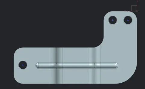
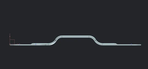
BEAD – sketching a bead of 255mm along the bracket, having depth=7mm, radius=7mm and die radius=5mm.
REBEND
LOCAL RADIUS ANALYSIS
HOLE – M22 used.
DRAFTING
TOOLS AND FEATURES USED ON SHEETMETAL TO DESIGN BOX ASSEMBLY
- Sketch
- Normal Cutout
- Contour Flange
- Break corner
- Unbend
- Hole
- Bead
- Re bend
- Drafting
- Base view
TOOL AND FEATURE DESCRIPTION
- SKETCH
It is a 2d representation of a 3d part. It includes entities like line, rectangle, spline, circle, etc. It is a predetermined drawing with dimensions and relations.
- CONTOUR FLANGE
It is created with one or more edges at specified location. The minimum flange length must be at least four times the thickness of the sheet metal. Bend radius is equal to the sheet metal thickness.
- NORMAL CUTOUT
This command is to remove the desired shape of material. Removal sketch can be drawn on the sheet metal face, wherever required.
- BREAK CORNER
This command gives a smooth finish over the corners of the sheet metal part.
- UNBEND
It makes the part unbend, that is all the features done are made flat. This is useful while sketching on the corners and bend areas.
- BEAD
It lifts material along contour sketch.
- REBEND
This command puts back all the bends already created also along with new features included while in unbent state.
- DRAFTING
This command is to have 2D drawing of the sheet metal part created.
- BASE VIEW
It specifies the location, orientation, view and scale of the part for drafting.
BRACKET STANDARD VIEWS
TOP VIEW
FRONT VIEW
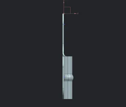
SIDE VIEW
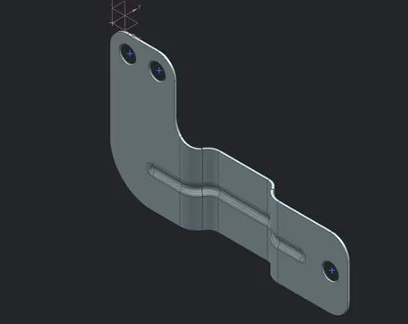
ISOMETRIC VIEW
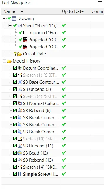
FEATURE TREE
DRAFTING
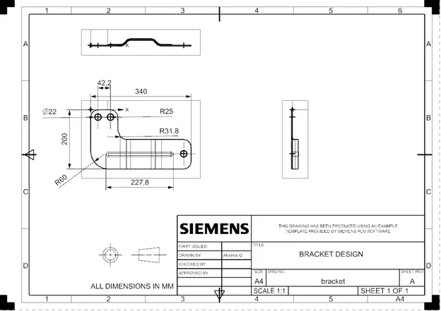
The 2D drawings were created on an A3 sheet.
Scale ratio = 1:2
CONCLUSION
Hence the bracket sheet metal part is created using NX12 software.