Advanced Sheet Metal Design Using NX Cad Challenge_6_Bracket
DESIGNING OF SHEET METAL BRACKET USING NX CAD
OBJECTIVE:
To design sheet metal Bracket using siemens NX-CAD.
INTRODUCTION:
Sheet metal is metal formed by industrial process into thin flat pieces.Sheet metal is one of the fundamental form used in metalworking and it can be cut and bend into variety of shapes.The thickness of the sheetmetal varies from 0.5mm-6mm.Sheet metal can be made from variety of material including aluminum,steel,copper etc.It is extremly strong and durable.
Siemens NX software is a flexible and powerful integrated solution that helps you deliver better products faster and more efficiently. NX delivers the next generation of design, simulation, and manufacturing solutions that enable companies to realize the value of the digital twin.
The NX CAD is formerly known as unigraphics is an advanced high end CAD/CAM/CAE software which has been owned since 2007 by Siemens PLM software.
DESIGN APPROACH:
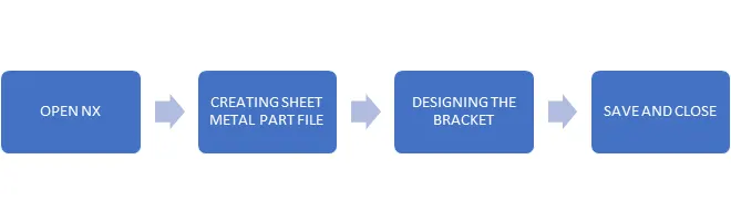
DESIGN METHODOLOGY:
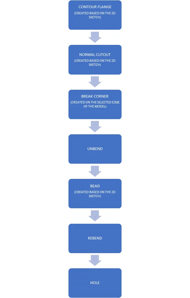
DESCRIPTION OF TOOL /FEATURES USED TO CREATE CASING DESIGN
Contour flange:
Creates a flange by extruding a sketch along a direction or add material by sweeping a sketch along a edge or chains of edges.Contour flange can also used as base feature of a new sheetmetal part or add the contour flange as secondary feature.Contour flange is cerated only in opened sketch.
Bead:
Bead command is used to lift material along the contour of a sketch that simulates a stamping tool.It also creates a solid using path and a cross section shape.It is also used to stiffen sheet metal.
Normal cutout:
Cuts material by projecting the sketch on to the model and then cutting perpendicular to the faces intersect by the projection.
Break corner:
The break corner tool is used to remove the sharp edge and convert it to round edge.
Unbend:
This tool is used to flatterns a bend and the materials adjusent to the bend.
Rebend:
Restores an unbend feature to its previous bend state along with any features added after unbend feature.
Holes:
Add a hole to one or more solid bodies in a part or assemblies with the option for counterbore,countersunk and threaded.
STANDARD VIEW OF THE MODEL:
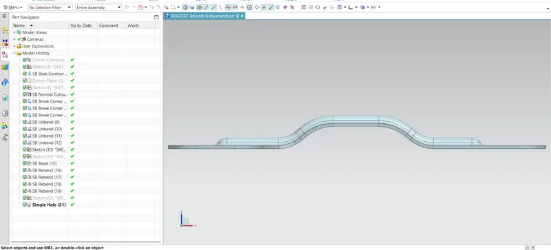
Front view:
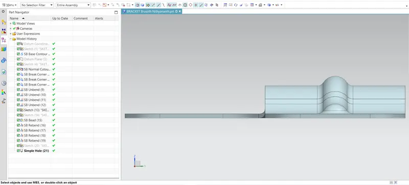
Right side view:
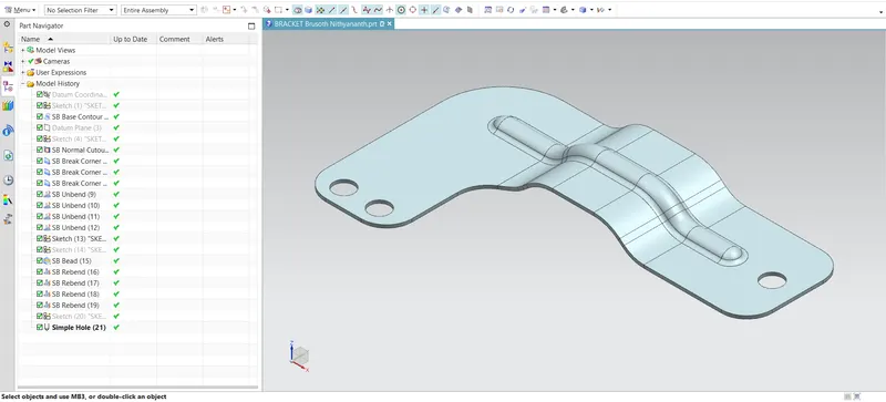
Isometric view:
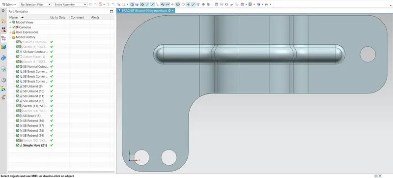
Top view
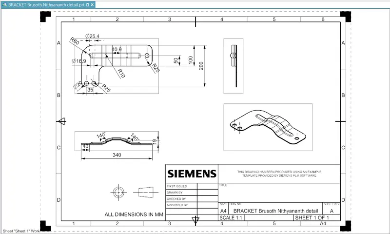
DETAILED VIEW
CONCLUSION:
Thus the sheet metal bracket is designed using Siemens NX-CAD.