Advanced Sheet Metal Design Using NX Cad Challenge_5_Odd Shaped Enclosure
DESIGNING OF ODD SHAPED ENCLOSURE USING NX CAD
OBJECTIVE:
To design the odd shaped enclosure using siemens NX CAD.
INTRODUCTION:
Sheet metal is a metal with a small thickness ranging from 0.5-6mm.Which is made flat and thin by rolling or hammering process.sheet metals are widely used in the manufacturing industry due to its various various advantages.
The NX CAD is formerly known as unigraphics is an advanced high end CAD/CAM/CAE software which has been owned since 2007 by Siemens PLM software.
Siemens NX software is a flexible and powerful integrated solution that helps you deliver better products faster and more effectively.NX delivers the next generation of design,simulation,and manufacturing solutions that enable companies to realize the value of the digital twin.
DESIGN METHODOLOGY /APPROACH:
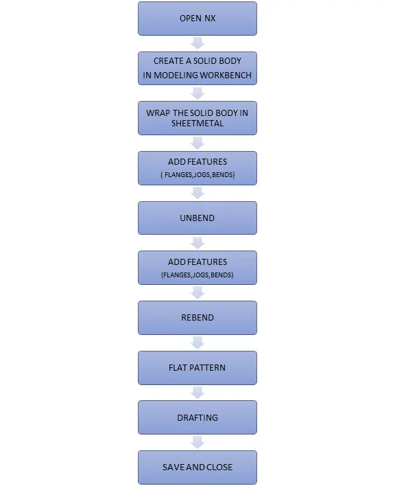
DESCRIPTION OF TOOL /FEATURES USED TO CREATE CASING DESIGN:
Tab:
Creates a base feature by extruding the sketch along a direction by a thickness value or by adding material to existing faces and bend regions of sheetmetal parts.The tab acts as a base feature upon which the bend,flange,hem etc are created.
Normal cutout:
Cuts material by projecting the sketch on to the model and then cutting perpendicular to the faces intersect by the projection.
Adding bends:
Flange:It is used to add flat flangeat an angle to a planar face and add the bend betweent the two.The flange consists of webs and bend.The flange is created on the edge of the base,flange,hem etc. The length angle of the flange can be adjusted.
Bend:Modifies the model by bending the material on one side of the sketch line,adding the bends between the two sides.
Break corner:
The break corner tool is used to remove the sharp edge and convert it to round edge.
Unbend:
This tool is used to flatterns a bend and the materials adjusent to the bend.
Rebend:
Restores an unbend feature to its previous bend state along with any features added after unbend feature
Holes:
Add a hole to one or more solid bodies in a part or assemblies with the option for counterbore,countersunk and threaded.
Dimple:
Lifts an area of the model inside a sketch that simulates a stamping tool.The direction of the dimple is also reversed.
Bead:
The sketch for beads must be tangent and continues.The bead tool is used to lifts material along the contour of a sketch that simulates a stamping tool.
Mirror:
The mirror tool is used to create copies of a feature or body and mirror it across the plane.
SHEET METAL FROM SOLID:
This tool is used convert non sheet metal part into valid sheet metal part.
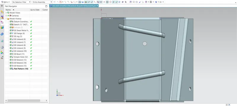
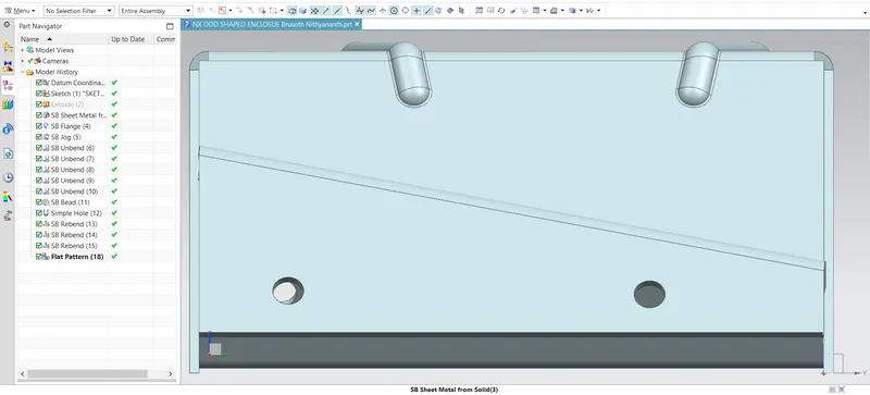
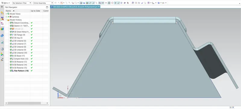
STANDARD VIEWS OF THE MODEL:
TOP VIEW
RIGHT SIDE VIEW
FRONT VIEW
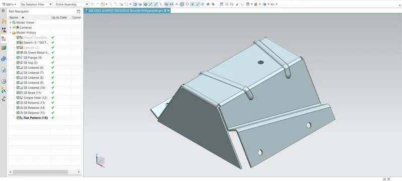
ISOMETRIC VIEW
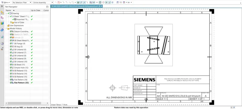
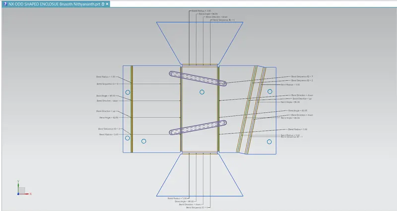
DETAILED DRAWING:
conclusion:
Thus the design of Odd Enclosure is completed using siemens NX-CAD.