Photo Realistic Rendering
MODELING OF AMERICAN CHOPPER IN SOLIDWORKS
INTODUCTION:
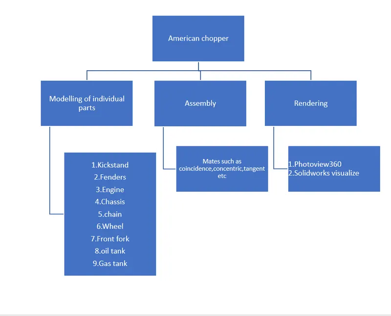
Solidworks is one of the prominent modelling software avaliable today this software is mainly used to model 3D parts using 2D sketch.It also has the option to specify the material and look of the model which we created.It has other ADD-in features like photoview360 which helps in rendering of the final model to make it look photo realistic. In this project we learnt about detailed design of Americal chopper parts and assemblig them and rendering the final after assembly.
OBJECTIVE
The main objectives of this project are:
- To create individual parts of chopper using solidworks
- To assemble all the individual parts into chopper
- to know the application of decals,lights and camera etc
To create photorealistic model and render it using photoview 360 and solidwork visualize
DESIGN METHODOLOGY /APPROACH
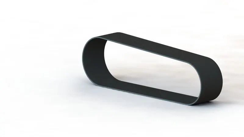
TRANSMISSION BELT:
Features used to create Transmission belt
- sketch
- Offset
- Extruded Boss/Base
- Fillet
- Appearance
Sketch
Sketch tool helps to create 2D drawing of 3D model.The sketcher workbench contains tools such as line,circle,rectangle etc . Inorder to awake sketcher workbench we need to select drawing planes.There are three Planes namely front,top and right plane.The sketch should be fully defined before extruding it.
Offset
Offset is used in sketcher workbench .The offset tool helps to copy the sketch to a specified distance from the orginal sketch.
Extruded Boss/Base
It is a material adding tool which add material in x,y,z, direction and helps to converts 2D drawing into 3d part.The extrude feature is applicable only when the sketch is in closed condition.After drawing a sketch when you select extrude option it automatically open its property manager.The property manager gives you option about how the sketch should extruded.
Fillet
The fillet converts sharp edge into into curved shape .This fillet option is availabele in both sketch and part workbench.In part workbench the fillet is available only after extruding a the sketch.There are various type fillet available such as constant size fillet,variable size fillet,face fillet,full round fillet .
constant size fillet:
It has only one radius throughout the edge ot the fillet
Variable size fillet:
Here more than one fillet radius can be applied.
Face fillet:
The face fillet is used to create fillet between the faces of the extruded part.
Full round fillet:
This fillet takes place between three faces of an ectruded part here the fillet radius is taken automatically.
Appearance
It helps to apply the colour of the metal,steel,glass etc to the extruded part.
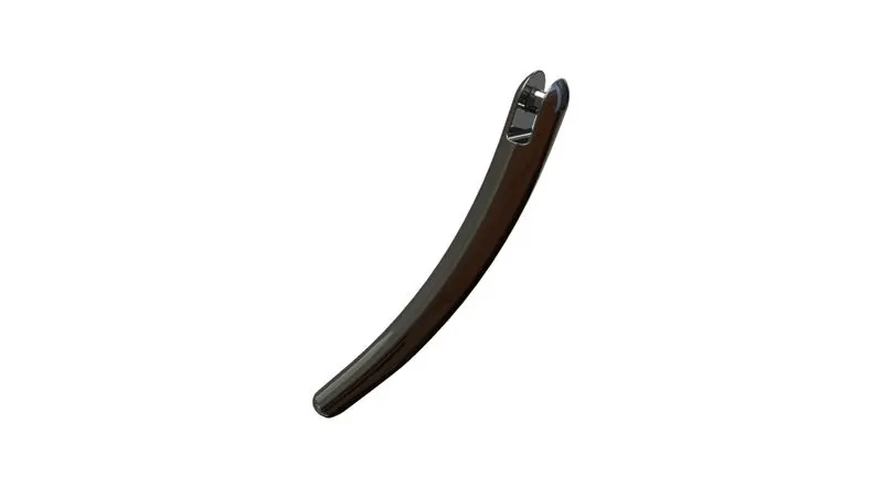
KICK STAND:
Tools and features used to create kickstand:
- Sketch
- Loft
- Dome
- Extrude boss
- Extrude cut
- Fillet
- Split
Loft:
Loft tool is used to create a single extruded part from two or more closed profiles (such as circle ,rectangle etc) . In the kickstand which we creates hear uses two slot stright(used as profile) which has different dimension which is connected by a spline(used as guide curve)to create the shape of the kickstand.To create a loft a guide curve or centre line parameter is required and the profile should be in contact with this guide curve or centre line parameter.The loft tool is used to create complex part.The loft is also used to extrude between different shaped profiles that lies on different sketch planes.
Dome:
The dome tool is used generate curved shape at the selected extruded face.The dome tool is availabe only after a extruded part is created.
Extrude cut:
The extrude cut is a material removing tool.Initially this tool is not active.This tool gets awakned only after a extruded part get created.The extrude cut is opposite to extrude boss.It is used to remove material based on the profile selected for extrude cut.The extrude cut used in this kickstand to cut the profile at the top of the kick stand .Here the direction of the cut is through all both this means the cut takes place to the exreme end of the part in both direction.
Split:
The split tool is a meterial removing tool.To create split we can use both close and open profile.when two or more bodies intersect each other the split tool is used to cut unwanted part and gives a clean look.
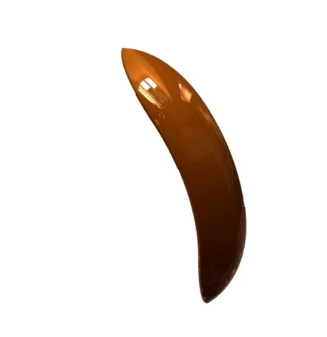
FRONT FENDER:
Tools and features used in front fender:
- Sketch
- Ofset entities
- Trim entities
- Revolve
- Dynamic mirror
- Split
- Appearance
Trim entities:
Trim entities is used in sketcher work bench.It helps to remove unwanted sketches which intersect each other.
Extend entities helps broken entities to intersect each other.
Revolve:
The revolve tool is used to extrude the profile in 360 degree about the axis of rotation this degree can be adjust based on requirement.The degree of rotation of the profile can be controled by adjusting the angle in the direction dialoge box.The temporary axis can also be selected as the axis of revolvation.when both direction 1 and direction 2 dialogue box is selected at the same time the maximum degree of revolvation at each is maximum 180 degree.The maximum portion of the the front fender is created using revolve tool.
Dynamic mirror:
The mirror tool is available in both skeacher and part workbench.The mirror tool is used to create the copy of selected part or sketch across the referance line or plane.
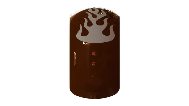
REAR FENDER:
Tools and features used to create rear fender
- Sketch
- Offset entities
- Trim entities
- Revolve
- Appearance
The tools and features used in rear fender is similar to the front fender.
CHAIN:
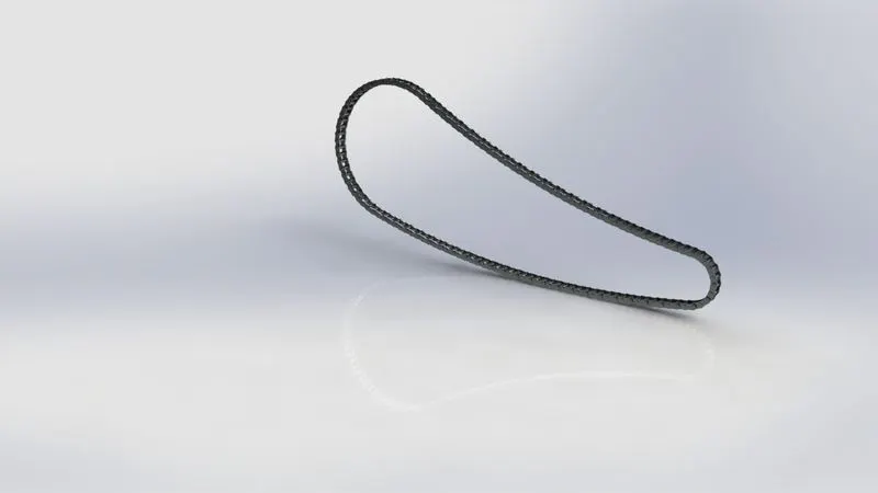
Tools and features used to create chain
- Sketch
- Trim
- Fillet
- Block
- Extrude Boss
- Patterns
- Appearance
Blocks:
A block is a saved sketch that can prevent redrawing same sketch multiple times.
Steps to create a block
- Create a sketch
- seleck make block(Tools<Block
- Select entities that u want to make block
- click ok and save the block
Patterns:
The pattern helps to produce copies of a part and also arrange them bsase on our requirement with equal distance between each copy or variable distance between each copy. Here the pattern is used to produce large number of copys of the chain links and arranged them in a specific direction.
Extrude Boss
selected contours a sub option in the extrude boss plays a major role in extruding the chain links.The selected contours is a selection tool used to select closed profiles which is present between two or more intersecting profiles.
OIL TANK:
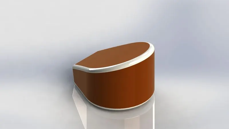
- Sketch
- Boss extrude
- combine
- Fillet
- Shell
Combine:
The combine tool is use to combine two or more individual body into a single body.It also has options such as add,substract,common.
Add:
The add option is used to combine multiple solid body into single solid body.This option generally used to generate complex body.
Substract:
This tool will remove material from solid body based on the geometry of one or more body.
Common:
This tool help to generate singular body based on the intersection of multiple bodies.
Shell:
The shell tool hollows out a part leaves open the face selected and create thin walled feature on the remaining faces.If ther is no faces selected on the model you can you can shell the solid part creating closed hollow model.
PEDAL:
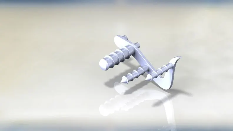
Tools and features used to create Pedal
- sketch
- Extrude
- Fillet
- Linear pattern
- Chamfer
- Dome
Linear pattern:
The linear pattern is used to create multiple instance of one or more features that you can space uniformly in one or two linear paths.Here the distance between each instance can also be specified.The direction of the pattern can also specified by using the edge,referance axis etc.
Chamfer:
The chamfer tool is used to create beveled edge on the selected,vertex,face,edge of the model.The chamfer is availabe in both sketcher and part workbench.The commonly used chamfers are distance distance chamfer and angle distance chamfer.
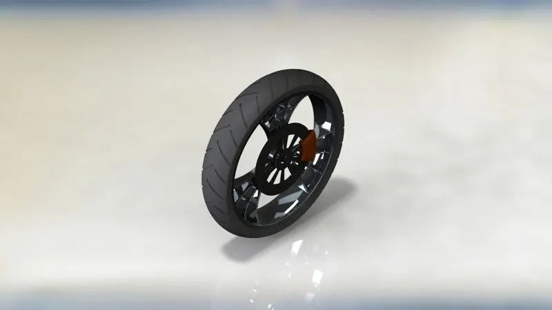
FRONT WHEEL:
Tools and features used to create front wheel
- Sketch
- Revolve
- Trim
- Fillet sketch
- Boss extrude
- Revolve cut
- Linear pattern
- Chamfer
- Cut extrude
- circular pattern
Revolve cut:
The revolve cut tool is used to remove the material from a extruded part by revolving around the extruded part in an axis of revolvation.To perform a revolve cut a profile and the axis of revolvation is required.To perform the revolve cut the profile and the part for which the material should be removed are in contact.The degree of rotation can be adjust using direction dialogue box.
Circular pattern:
The circular pattern is used to create multiple instance of one or more features that you can space uniformly in circular paths.Here the distance between each instance can also be specified.The direction of the pattern can also specified by using referance circle.
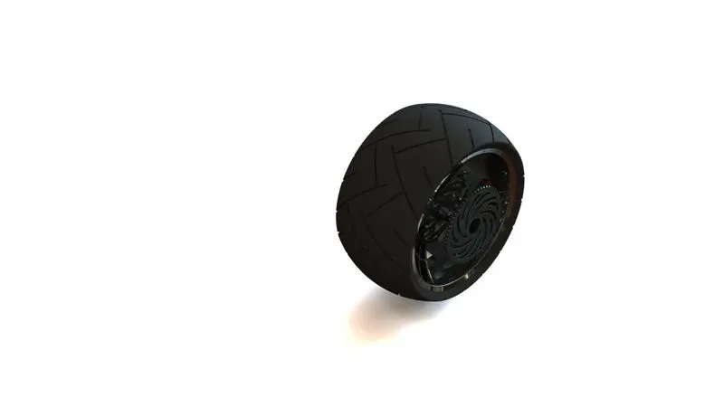
REAR WHEEL:
- Sketch
- Revolve
- Trim
- Fillet sketch
- Extrude boss
- Planes
- Revolve cut
- Linear pattern
- Chamfer
- Extrude cut
- Fillet feature
- circular pattern
PLANES:
Planes are used to sketch the profile.Initially there are top,front,right planes available in solidworks we can also create planes based on our needs by using referance section.
Chamfer:
The chamfer tool is used to create beveled edge on the selected,vertex,face,edge of the model.The chamfer is availabe in both sketcher and part workbench.The commonly used chamfers are distance distance chamfer and angle distance chamfer.
Extrude cut:
The extrude cut is a material removing tool.Initially this tool is not active.This tool gets awakned only after a extruded part get created.The extrude cut is opposite to extrude boss.It is used to remove the material based on the profile selected for extrude cut.The extrude cut used in this kickstand to cut the profile at the top of the kick stand .Here the direction of the cut is through all both this means the cut takes place to the exreme end of the part in both direction.
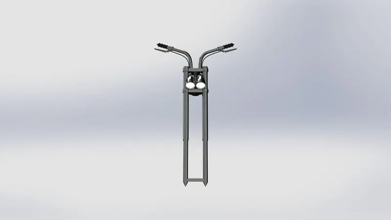
FRONT FORK:
Tools and features used for front fenders
- Sketch
- Extrude Boss
- Extrude cut
- Trim
- Revolve
- Split
- Move/Copy bodies
- Dome
- Mirror
- Combine
- Projected curve
- Sweep
- Revolve cut
- Fillet
Split:
The split tool is a meterial removing tool.To create split we can use both close and open profile.when two or more bodies intersect each other the split tool is used to cut unwanted part and gives a clean look.
Sweep:
The sweep tool is use to extrude a profile along a path.The profile may have one or more contour.The profile used for sweep should be a closed profile.The extrude path may be a curve,spline,line etc.To create a sweep the path and the profile should be in contact with each other.
Projected curve:
The projected curve tool is used to convert the 2D curves in two different planes of projection into a 3D curve.
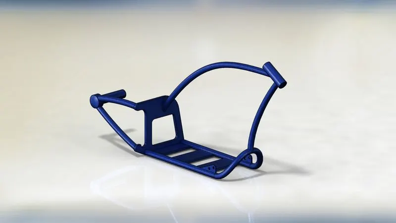
CHASSIS:
Tools and features used to create chassis
- Sketch
- Offset
- Convert entities
- Project curves
- Trim
- Sweep
- Split
- Revolve
- Cut Extrude
- Combine
- Convert entities
Convert entities
It allow to make a copies of the projected sketch,face,edge onto to the active sketch plane.
Combine:
The combine tool is use to combine two or more individual body into a single body.It also has options such as add,substract,common.
Add:
The add option is used to combine multiple solid body into single solid body.This option generally used to generate complex body.
Substract:
This tool will remove material from solid body based on the geometry of one or more body.
Common:
This tool help to generate singular body based on the intersection of multiple bodies.
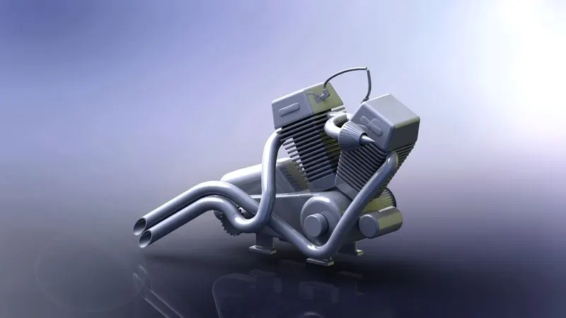
ENGINE:
The tools and feature used to create engine
- Sketch
- Trim
- Revolve
- Boss Extrude
- Extrude cut
- Offset
- Dome
- Fillet
- Projected curve
- Composite curve
- Sweep
- Mirror
- Circular pattern
- Split
Composite curve:
The composite curve is used to joint two curve and make them into single curve.
Projected curve:
The projected curve tool is used to convert the 2D curves in two different planes of projection into a 3D curve.
Sweep:
The sweep tool is use to extrude a profile along a path.The profile may have one or more contour.The profile used for sweep should be a closed profile.The extrude path may be a curve,spline,line etc.To create a sweep the path and the profile should be in contact with each other.
Circular pattern:
The circular pattern is used to create multiple instance of one or more features that you can space uniformly in circular paths.Here the distance between each instance can also be specified.The direction of the pattern can also specified by using referance circle.
GAS TANK:
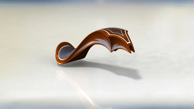
Features and tools used to create gas tank
- Trim
- Projected curve
- Sweep surface
- Loft surface
- Fill surface
- Surface Trim
- Surface Knit
- Sweep cut
- Fillet
Sweep surface:
This tool is available in surface workbenck of solidworks.The sweep tool is used to create surface by sweeping the profile along the guide curve.To create a sweep surface a profile and a path/guide curve is necessary.To create a sweep surface the guide curve and the profile must be coincide/pierce with eachother.
Loft surface:
The loft surface is available in surface workbench of solidworks.The loft surface is used to create surface between between different profiles where each profiles lies in different sketching plane.It also uses guide curve.It also generate surface between the curves which sketched in different planes.
Fill surface:
This tool is used to create fill surface between number of boundary segments.The boundary segments may be planar or non planar but there should not be a gab more than 0.1mm between consecutive boundary segment.The fill surface is used to create surface to fill the gap of the model.
Surface trim:
when two more surface are intersecting the surface trim tool is used to trim unwanted surface.
Knit surface:
The knit surface is used to merge the gap between the surfaces.
Sweep cut:
It is a material removal tool .It remove the material by moving the profile along the path.The profile of cut must in contact with both path and extruded path .The shape of the cut is based on the sweep profile.
ASSEMBLY OF CHOPPER:
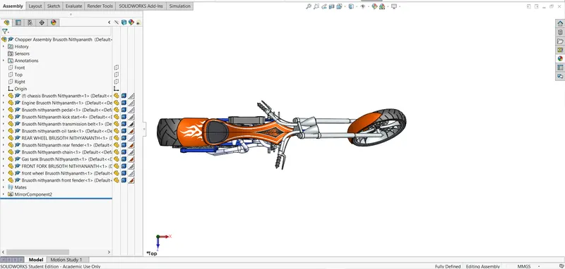
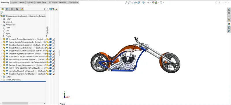
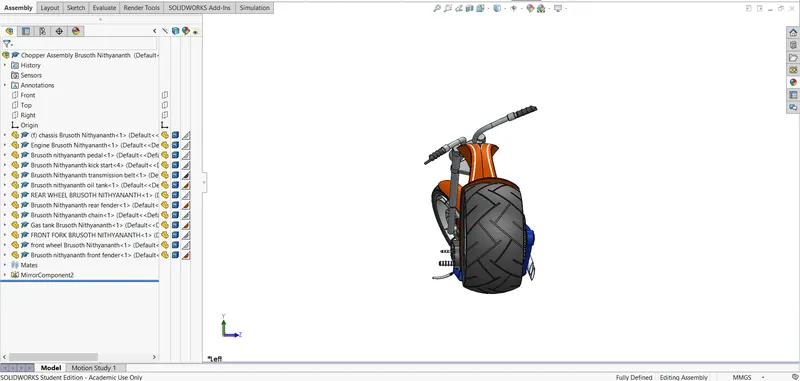
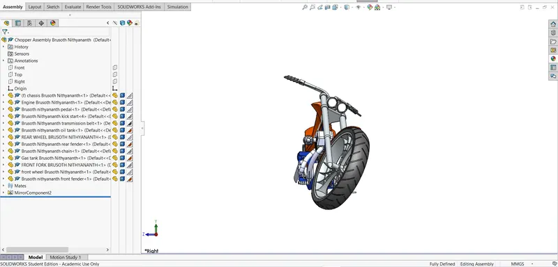
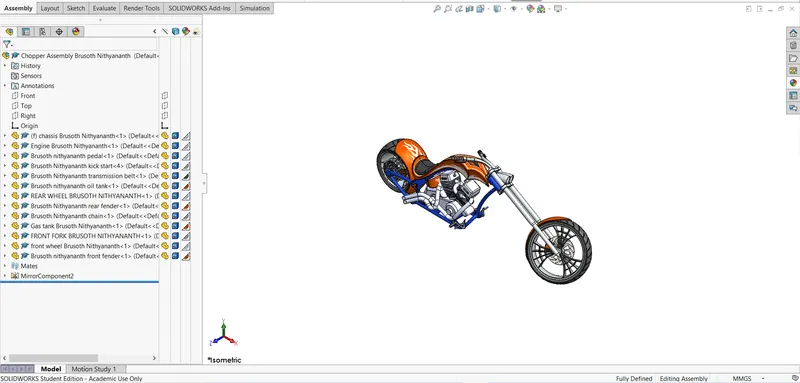
In assembly workbench all the individual parts of the chopper is assembled togather to form the final American Chopper.This assembly is made by the use of mates.
Initially the chassis is inserted into the assembly workbench and also it is used as the base part which means the other individual parts are assembled by using this as referance.The top,front,side planes of the assembly workbench and the respective planes of chassis is made coincide.
Mates are the geometrical relation between the assembled components.Mates are added to define the allowable direction of linear or rotational motion of the component
The mates used to create the assembly are discussed below:
1.Coincidence mate-The coincidence mate is used coincide or make contact between two parts,planes.It also bring the parts parallel to each other.
2.Concentric mate-It helps the circular faces of two parts to share same centre point.
3.Tangent mate-It helps to make contact with circular faces.
4.Limit angle mate-It is a advanced mate type that allows to specify the range of angular values a component is able to move.
5.Width mate-When width mate is applied between two parts the two faces of each parts must be selected this helps to bring one part at the centre of other part.
6.Parallel mate-Parallel mate is used to two faces,parts,planes parallel to each other.
7.Distance mate-The distance mate is used to apply distance between two faces,parts,planes.
RENDERING:
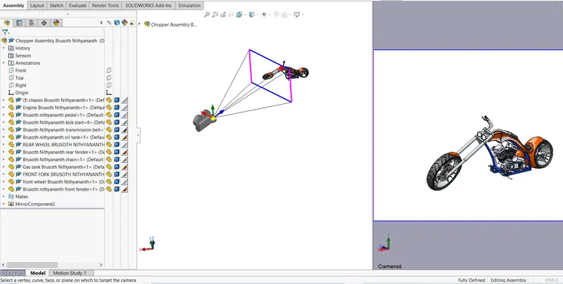
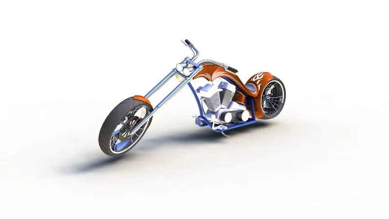
Rendering is the process of creating realistic image of the photorealistic model with the environment.The rendered image incorporates the appearance,lighting,scenes and decals included with model.In photo realistic model some of the mates and conditions are changed to render the realistic model.
Rendering has done in two ways in solidworks:
- Photoview 360
- Solidworkes visualize
Photoview 360:
Photoview 360 is solidworks Add-in that produce photorealistic rendering of solidworks model.The rendering image incoporates appearance,lighting,decals,scenes included with the model.
Lighting:
It is used to add special lighting effect such as caustic and to iluminate specific area of the model.To control shadow direction and strength.
Camera:
It is used to specify the position of the model.
SOLIDWORKS VISUALIZE:
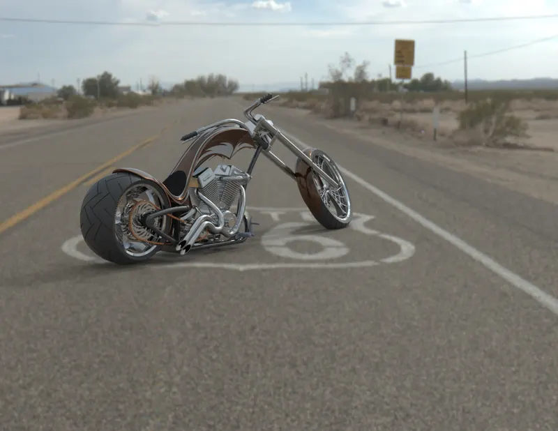
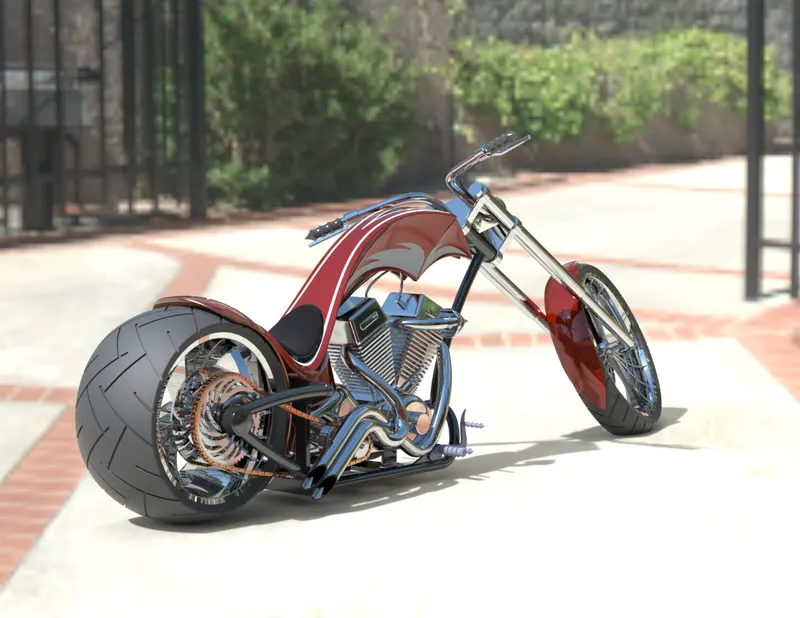
Solidworks visualize provides a suit of stand alone software tools that combine industrial oriented rendering capabilities with visualize design oriented features and workflows allowing easy and fast creation of visual content that communicates a design vision passion and emotion.
Environment:
It is the background of the model which helps to show the part model as photorealistic model.
Appearance:
The appearance helpd to add colour to the model.
CONCLUSION:
- The parts of the American chopper are modeled by using various tools available in solidworks.
- The modelled parts of the chopper are assembled in assembly workbench by using mates.
- The assembled parts are rendered using photoview 360 and solidworks visualize.