Radar Mast & Final Assembly of Yacht
SURFACE MODELLING OF SUNSEEKER PREDATOR YATCH
OBJECTIVE:
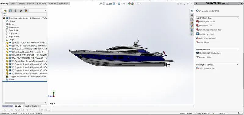
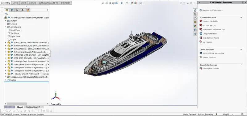
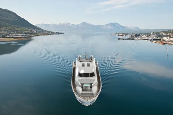
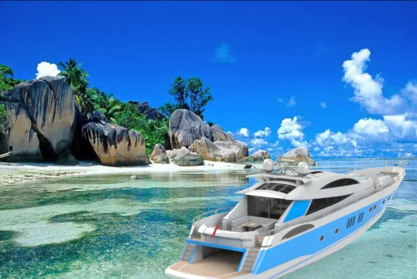
The objective of this project is to design and model all parts of sunseeker Predator yatch and assembling it to create photorealistic rendering of yacht.
INTRODUCTION:
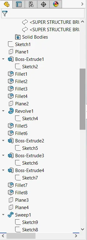
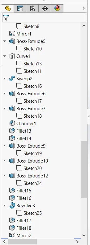
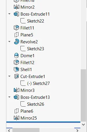
In this project the sunseeker predator yatch was taken as conceputal model to understand the 3D modelling methodology of solid modeling and surface modeling.Each and every part of the yatch was designed and modelled using solidworks.Then the modelled part were assembled by adding proper mates and constrains to create photo realistic rendering of yatch .
Solidworks is a mechanical design automation application that lets designers quickly sketch out ideas and experiment with features ,dimension and produce model and detail drawing.
The Photo View 360 is a solidworks ADD-IN that helps to create photo realistic rendering of solid works model.The rendered image incoprates the appearance,lighting,scenes and decals included with the model.
The solidworks visualize is a photo realistic rendering tool that uses our CAD data to create magazine quality images or commercial quality animation.
DESIGN APPROACH :

DESIGN METHODOLOGY:
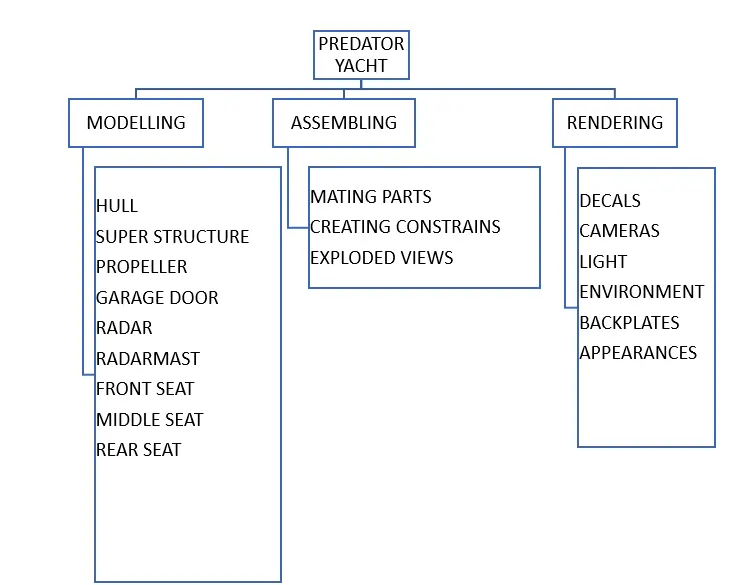
DESCRIPTION OF COMMENTS USED TO CREATE PREDATOR YACHT:
1.Extruded surface:
The extruded surface tool is used to extrude the sketch here there is no thickness for extrusion.The extrusion can be done in both direction.
2.Lofted surface:
The lofted surface is used to create surface extrusion between two or more profiles which have same or different shapes.
3.Revolved surface:
This tool is used to revolve the surface extrusion of about an axis of rotation .The angle of rotation can be controlled by adjusting the angle.
4.Swept surface:
The swept surface tool is used to create a surface extrusion of a profile about an path.The path used for the extrusion should be in contact with the profile.The swept surface can be created for both open and closed profile.
5.Filled surface:
This tool is used to patch the gaps with more than four edges as well as the gap with irregular shapes.
6.Boundary surface:
Boundary surface is used to create surface that can be tangent ,curvature ,continuous in both direction.
7.Ruled surface:
The ruled surface tool is used to create a surface that extend out in a specific direction from the selected edges.It also used to create drafted wall.
8.Knit surface:
The knit surface tool is used to combine two or more faces or surfaces into one.It is also used to control the gap,merge the surface faces and also convert surface into solid using create solid option.
9.Offset surface:
Offset surface tool is used to copy the surface to a distance from the orginal surface the offset can be copied in both direction.
10.Trim surface:
The trim surface is used remove the unwanted surface which intersect with eachother.The trim tool option acts as referance which helps to remove the intersecting surface.Here there are two option available such as keep selection, remove selection.The keep selection option is used to keep the selected option whereas the the remove selection option is used to remove the selected option.
11.Referance plane:
It is used to create plane based on our requirement by using plane,edge,face as referance to create the plane.
12.Mirror surface:
A mirror surface is a copy of selected feature or a body mirrored about the plane or planer face.Here when the orginal surface is modified it is automatically updated to the mirrored surface.
13.Projected curve:
The projected curve is used to produce 3d curve by comparing the different sketches drawn in different plane.There are two types of projected curve
14.Fillet:
The fillet tool is used to convert the sharp edge into curved edge.
Features used to create yacht:
1.Boss extrude :
It is a meterial adding tool which adds material in x,y and z direction and helps to convert 2d sketch into 3d part.
2.Extruded cut:
Extrude cut is a material removing tool.It used to remove the material based on the profile selected for extrude cut.This tool get activated only after a extrude part gets created.
3.Split:
The split tool is used cut the selected face,part from a complex design by using a closed or open profile
4.Dome:
The dome tool is used to generate a half shaped sphere at the selected extruded face.
5.Swept Boss/Base:
Here a profile is made to extrude along a path.The profile is sketched in different sketch planes.Both the profile and path should be in contact with each other .
6.Revolve Boss/Base:
This tool hepls to revolve the extrude about an axis of rotation.The angle of rotation can be adjust based on our needs using direction1,direction2 dialogue boxes.To perform the revolve boss the axis of revolvation should be selected based on which the revolvation is done.
7.Loft Boss/Base:
Loft tool is used to create a extrude between two or more closed profiles which may be same or different in shapes.There is a green green shaped ball which should be on the same side otherwise there will be deformation in the shape.
PART MODELLING DESCRIPTION:
BLUEPRINT SETUP:
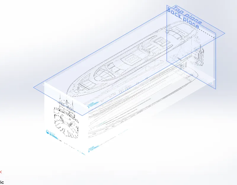
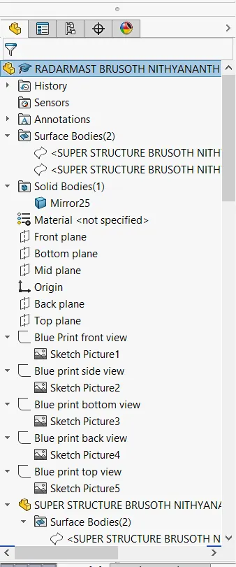
- Here the blue print of the different views (such as top,bottom,front etc)of the yacht is inserted in corresponding planes .
- Here the blue prints are imported by selecting the planes and enter into the sketching work bench and go to tools
- Two extra planes are created to insert two more views of the yatch.
PROPELLAR:
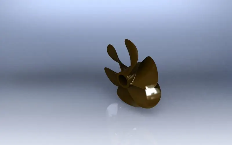
Comments used to create propellar
In sketch:
- Spline
- Line
- Circle
In features:
- Revolve Boss/Base
- Lofted Boss/Base
- Extruded cut
- Refefance plane
Modelling procedure:
- The centre portion of the propellar is sketched initially and revolved using Revolve Boss/Base
- A plane is created at a offset distance 360 from top plane and the sketch of the blade is sketched here.
- The second half of the blade sketch is sketched in the top plane and these two sketches are extruded using lofted Boss/Base tool.
- This blade is then circular patterened and fillet is applied on it.
- And the extrude cut is done to the the centre part.
RADAR
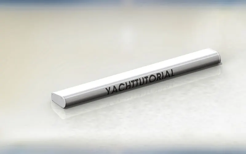
The comments used to create radar
In sketch:
- Line
- Text
- Circle
- Point
In features:
- Extruded Boss/Base
- Extruded cut
- Sketch pattern
- Fillet
- Mirror
- Split line
Modelling procedure:
- Sketching the profile of the radar body in right plane and extruding it using extrude Boss/Base
- Adding the required fillet to the extrude.
- By using sketching pattern the four dotted holes were created using Extrude Boss/Base and Extrude cut
- Now the body is mirrored using mirror tool using the right plane as mirroring plane.
- The text over the radar was created using the text option in the sketch and then the split line was used to generate over the face of the rador
- At last the radar must be filitted around the edges of the body also around the four holes
- Finally the radar was saved after applying proper appearance.
FRONT SEAT:
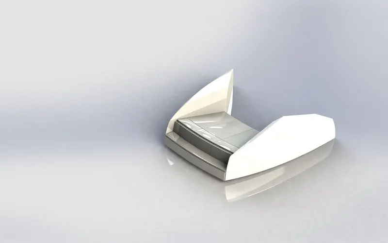
Comments used to create front seat
In sketch:
- Line
- Spline
- Circle
- Arc
In surfaces:
- Extruded surfaces
- Lofted surfaces
- Trim surfaces
- Filled surface
- Knit surface
- Swept surface
- Revolve surface
In features:
- Extrude cut
- Revolved Boss
- Chamfer
- Fillet
- Mirror
- Dome
Modelling procedure:
- The front seat of the yacht was also created using blueprint
- The first half of the front seat was modelled whereas the other half was mirrored using mirror tool.
- The body of front seat is was modelled using swep surface,extruded surface,fill surface and lofted surface.
- The four rest bed are created using Revolve ,dome,cut extrude.
- The fillet and chamfer are created in the required edges.
- Finally the appearance is given and the part file is saved.
MIDDLE SEAT:
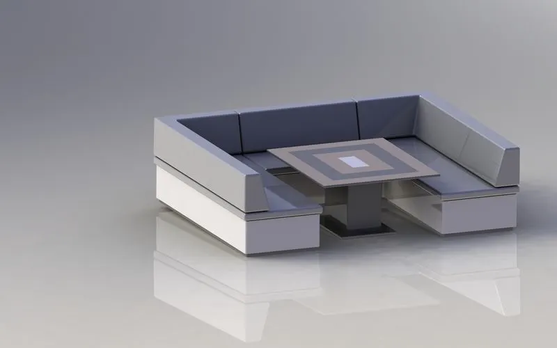
Comments used to create middle seat:
In sketch:
- Line
- Rectangle
- Offset
In features:
- Extruded Boss/Base
- Chmfer
- Fillet
- Mirror
- Referance plane
Modelling procedure:
- The middle seat is created using Extrude Boss/Base and applying chamfers and fillets as required.
- First mirror the base of the middle seat and then the seat of the mirror
- Now the table is created using referance plane, offset,extrude boss,mirror.
- The second half of the middle seat is created using mirror tool.
- Finally the appearance is given and the part file is saved.
REAR SEAT:
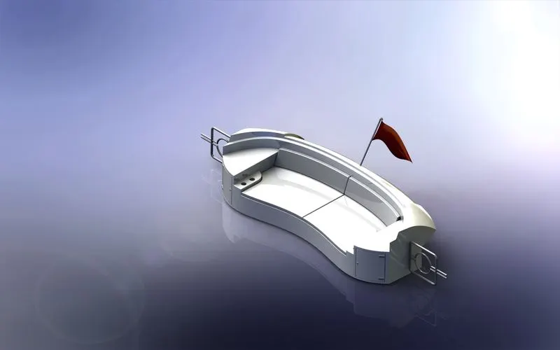
Comments used to create rear seat:
In sketch:
- Line
- Spline
- Circle
- Arc
- Rectange
In surface:
- Swept surface
- Extruded surface
- Offset surface
- Filled surface
- Knit surface
- Ruled surface
- Lofted surface
In features:
- Referance plane
- Extruded Boss/Base
- Revolved Boss/Base
- Fillet
- Mirror
Modelling Procedure:
- The main part of the rear seat is created using swept surface,offset surface,ruled surface,surface extrude.
- The seat was created using Extruded Boss,chamfer,offset surface,
- The flag post is created using Revolved Boss/Base and the flag was sketched using required 3d sketch and then this sketch is lofted to form the flag.
- The tail lamps are creted using extruded boss/base ,fillet and mirror tool.
- The steel gates for stairs are designed using referance plane and the swept surface.
- To fill the gap between the surface surface knit tool is used.
- The required fillet and chamfers where created before mirroring the seat
- Finally the required appearance are given and the part is saved.
HULL:
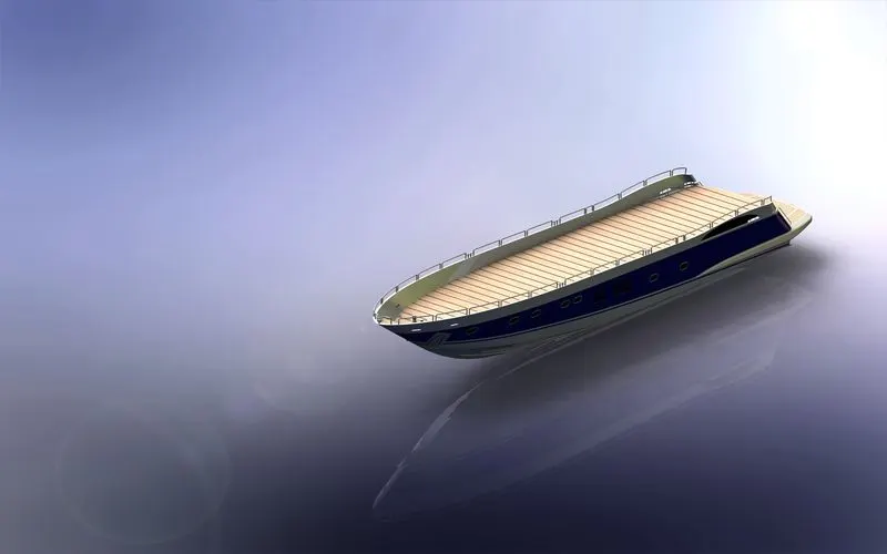
The hull consists of various parts such as anchor,deck,port,rig etc so we have to modell these parts along with hull.
Comments used to create hull:
In surfaces:
- Extended surface
- Lofted surface
- Revolved surface
- Surface trim
- Surface fill
- Surface knit
- Delete face
In features:
- Projected curve
- Chamfer
- Fillet
- Referance plane
- Split
- Split line
- Extruded Boss/Base
- Extruded cut
- Mirror
Modelling procedure:
- The first step in modelling hull is to insert the blue print setup.
- The shape of hull is obtained by using the help of projected curve .
- Now the curves are lofted to get the lofted surface and trimming the unwanted surface.
- Then the back portion of hull where the propeller need to be placed was extruded using extruded surface and the gaps between the surfaces are filled using knit surface.
- Then the offset option is used to create another surface and both surfaces was filled using fill surface option to create the outer shell of the hull which will be converted into a solid body atlast.
- Shell feature is used to create the front portion of the hull where the deck surface meets.
- The deck is created using extrude boss and cut extrude and then the chamfer and fillets are applied in the necessary location.
- All the windows and portholes were created using extrude hole and fillet is applied to its edges.
- To create a smooth edge around the berth window the referance planes were created and a circle is sketched in this plane and it is also pierced with the path which is a straight slot.
- The rails at the bottom of the yatch is created using Extruded Boss/Base and the chamfers are applied at both side.
- The cable roller were created using Extruded Boss/Base and swept Boss/Base and the head part is created using Revolved Boss/Base.
- Helix /spiral was created to sweep the rope around the cable.
- By using the slot the rope hanger were extruded and the dome was applied and then the linear pattern is used to create one more.
- The window bars were created using Extruded Boss/Base
- The staircase was created using extruded Boss/Base and the handle support is created using Swept Boss/Base.
- The railing around the hull is created using blueprints and projected curve .
- The axle of the propeller and surfer were created using revolved boss base and using 3d sketch.
- The half of the anchors were sketched and extruded and then the other half is mirrored.
- The garage portion is created using extrude cut and the portion was saved using split option.
- Now the hull is mirrored to create complete body of the hull.
- Finally the appearance is applied to the hull and it is saved.
GARAGE DOOR:
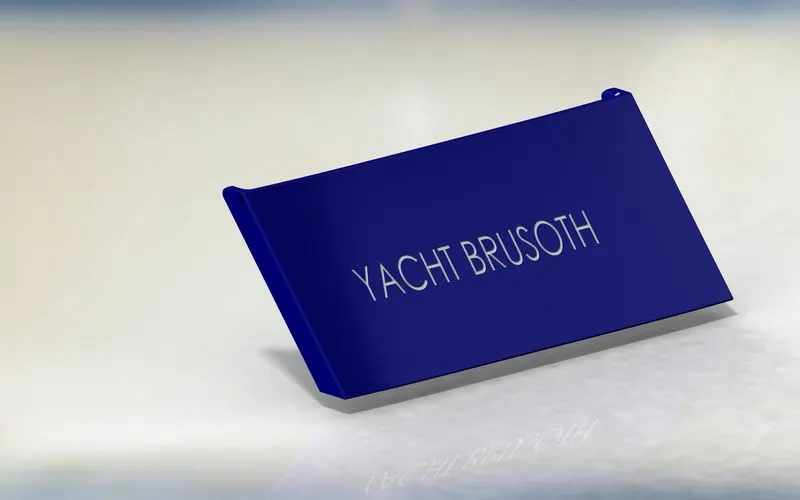
Comments used to create garage door:
In sketch:
- Line
- Spline
- Circle
- Text
In features:
- Extruded cut
- Referance plane
- Fillet, shell
- Mirror
Modelling procedure:
- The solid body split while creating hull was imported to model the garage door.
- By using extruded cut the part for garage door is created
- The by using shell feature the solid body of the gaurage door is created and the fillets are applied.
- Then the door holders is created by using cut extrude feature.
- The next half of the garage door is created by using mirror tool after appling the fillets.
- Now the text is written on the garage door by using text tool and extrude cut.
- Finally the appearance is given to the garage door and it is saved.
SUPER STRUCTURE:
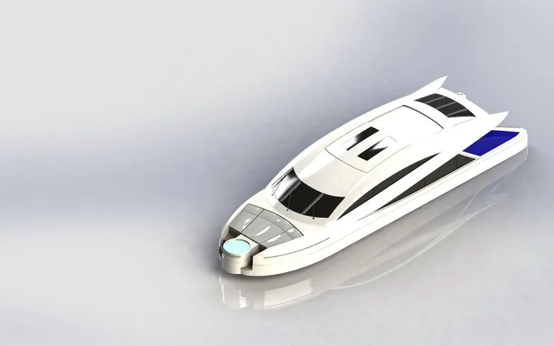
The comments used to create the super structure:
In surfaces
- Extruded surface
- Sweapt surface
- Ruled surface
- Knit surface
- Trim surface
- Extended surfaces
- Filled surface
- Lofted surface
- Revolved surface
- Fillet
- Chamfer
In features
- Project curve
- Referance curve
- Convert entities
- Split line
- Split
Modelling procedure:
- The deck surface of the hull is inserted and the superstructure is modelled over it.
- The side surface of the super structure was created using extruded surface,lofted surface,filled surface,trim and knit surface.
- Here the projected curve plays major role in giving the shape to super structure
- Also the gap between the surface is filled made into single suface by using knit surface.
- The windshield is created using extruded cut and wiper is created using 3d sketch and referance plane with the help of swept Boss/Bass
- The portholes for the superstructure were created by using extruded surface,trim surfaces and extended surfaces .
- The ruled surface was used to fill the left out the edges.
- The back door of the super structure was created using extruded cut,fillet and referance plane.
- Then all the surface are knited togather to form single solid body.
- The super structure consists of two surface bodies and five solid bodies.
- The half super structure is mirrored to create complete super structure.
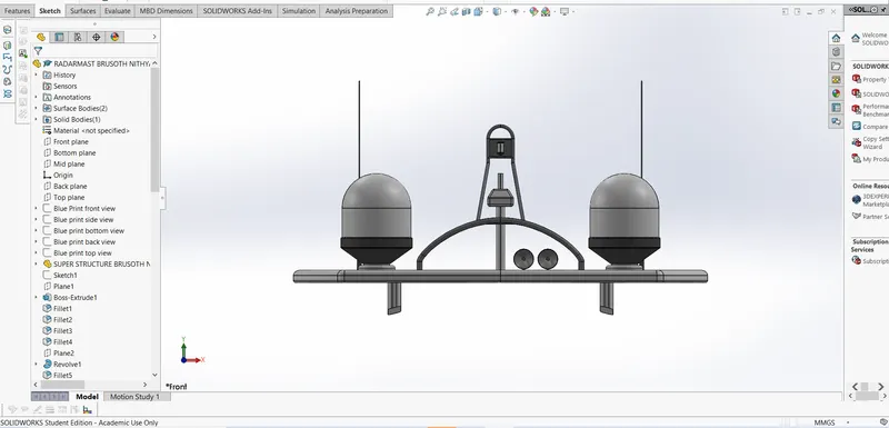
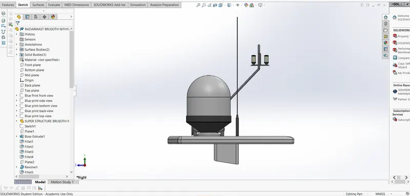
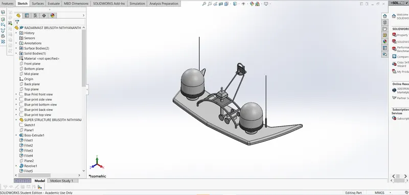
RADARMAST
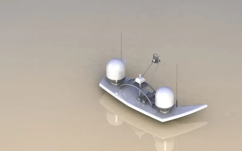
The comments used to create radarmast:
In feature
- Extruded Boss/Base
- Lofted Boss/Base
- Sweapt Boss/Base
- Revolved Boss/Base
- Referance plane
- Projected curve
- Fillet
- Dome
- Mirror
- Shell
Modelling procedure:
- The first half of the radar was modelled with the help of blue print and then the other half is mirrored using mirror tool.
- The body of the radar was created using extruded Boss/Base and revolved Boss/Base
- The antenna for the radar was also created using the extruded Boss/Base.
- The lamp stand alone with the connecting rod were created using the sweapt Boss/Base and the mirror tool.
- The lamp is projected using projected cure and then the curve was sweapt using sweapt curve.
- The horns were created using revolved Boss/Base,dome and shell.
- Then the fillet and chamfers were applied wherever necessary.
- Finally the part was saved by applying appropriate appearance.
ASSEMBLY:
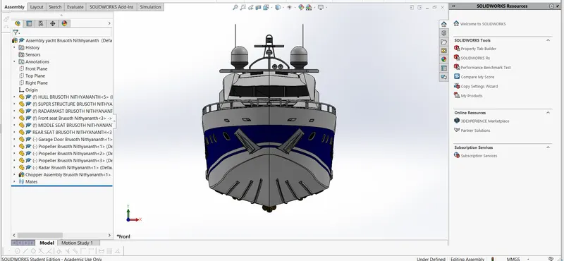
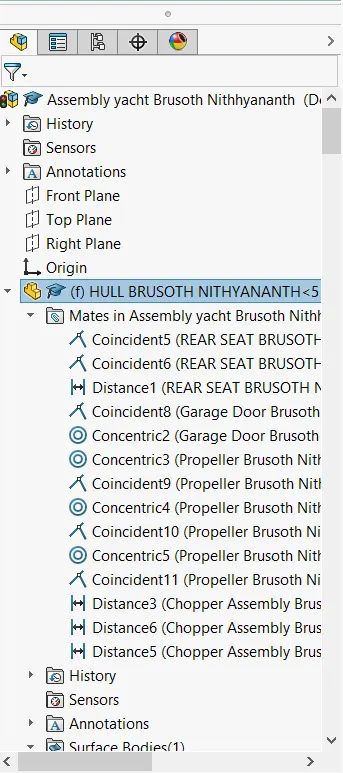
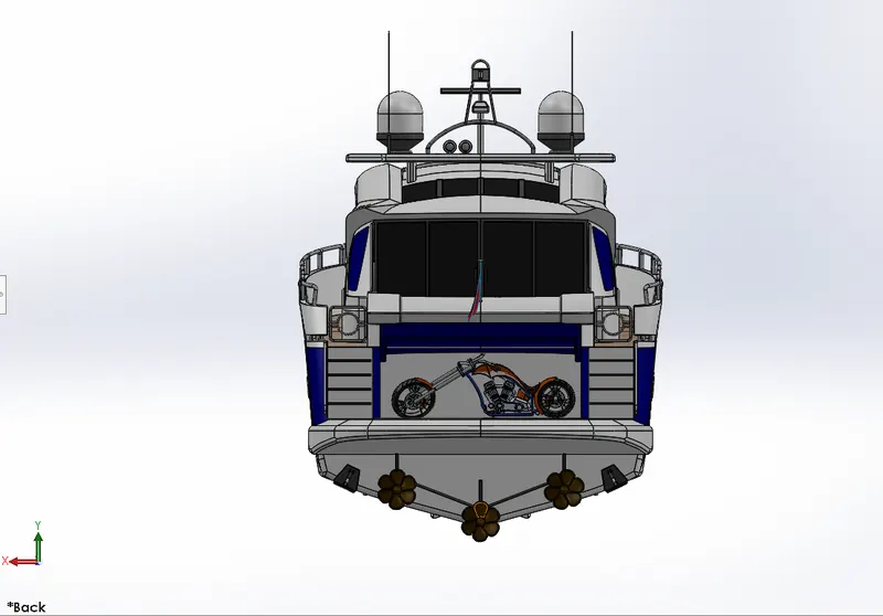
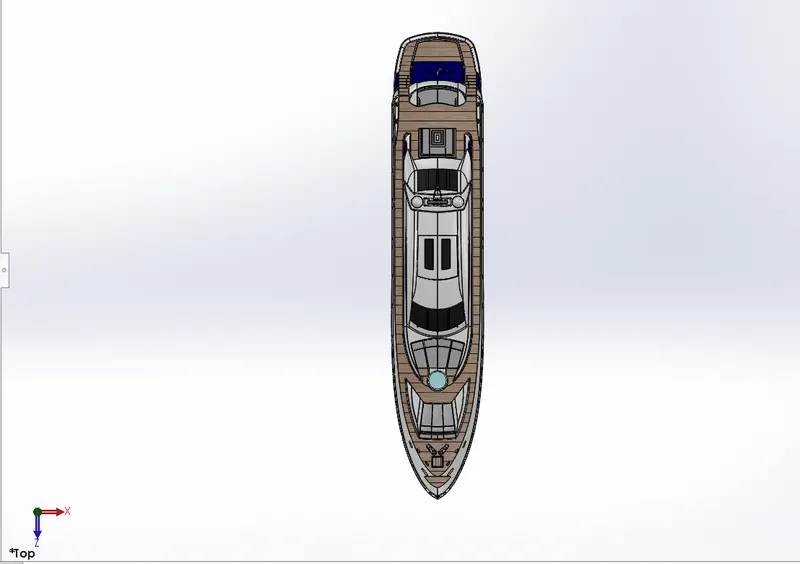
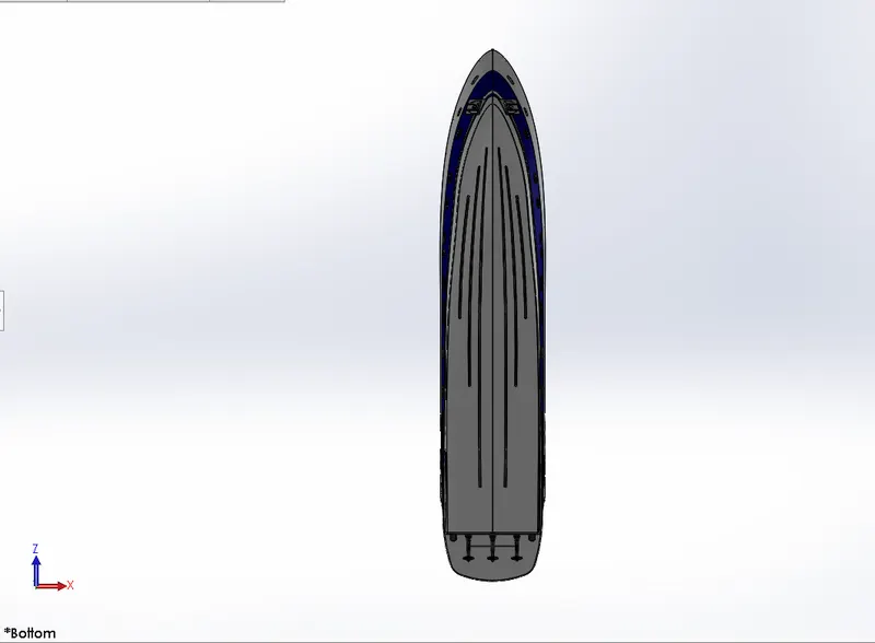
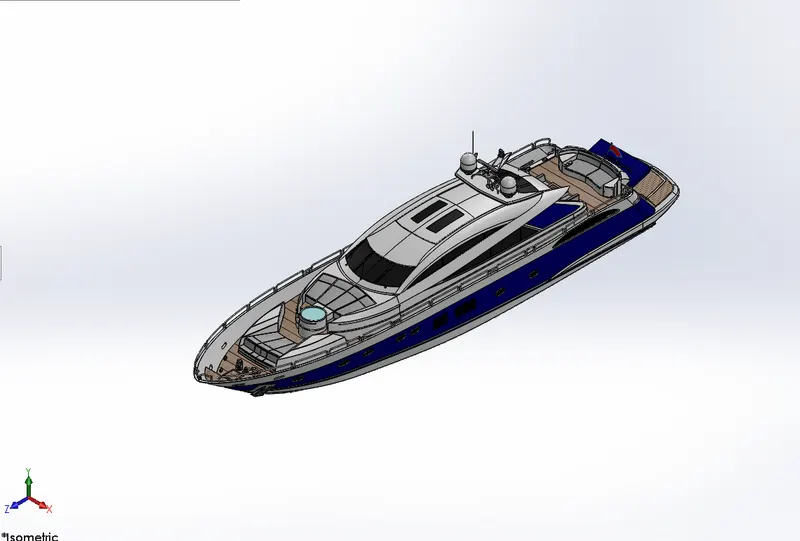
In assembly workbench each individual parts of the yacht is assembled to form the final yatch.Here the assembly is done with the help of mates and geometrical relation the commenly used mates are discussed below.
Coincident mates:The coincident mate is used to bring contact or coincidence between the parts or planes etc.
Concentric mates:The concentric mates used to share the shame centre point between the circular parts,faces etc.
Tangent mates:This mate help to make contact with circular faces,parts etc.
Distance mate:This mate hepls in applying distance between the parts, planes etc.
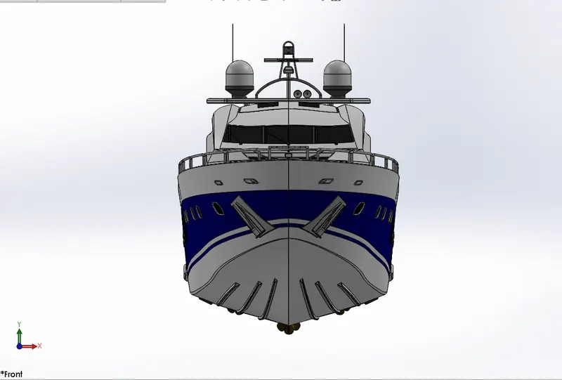
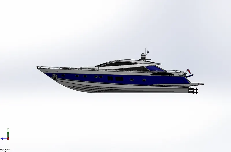
RENDERING:
The rendering of solidworks model is done using photoview 360 and solidworks visualize.
Photoview 360:
The photoview 360 is a ADD-IN present within solidworks for the purpose of photorealistic reandering within solidworks .This rendering incoporates lights,appearance,decals,scenes etc.It helps in easy and quick way to produce high quality rendering.
Environment:Environment can be lockedup as a background and can be applied in a similar manner as the appearance are applied to the parts.
Appearance:There are wide range of appearance available in photoview 360 than solidworks.Applying the appearance in photoview 360 is similar to applying appearance in solidworks.
Decals:Decals is the sticker or logo that can be applied on the model
Scenes:Each solidworks model is associated with photoview 360.For which you can specify properties such as environments and background.
Lighting:It is used to add special lighting effect such as caustic and to iluminate area of the model.It is also used to control shadow direction.
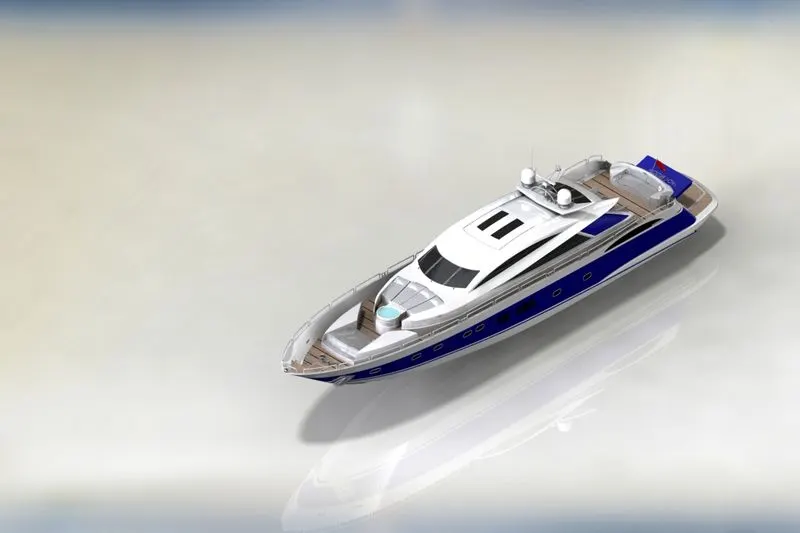
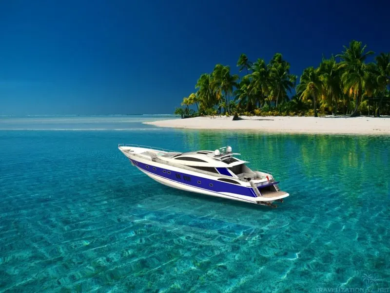
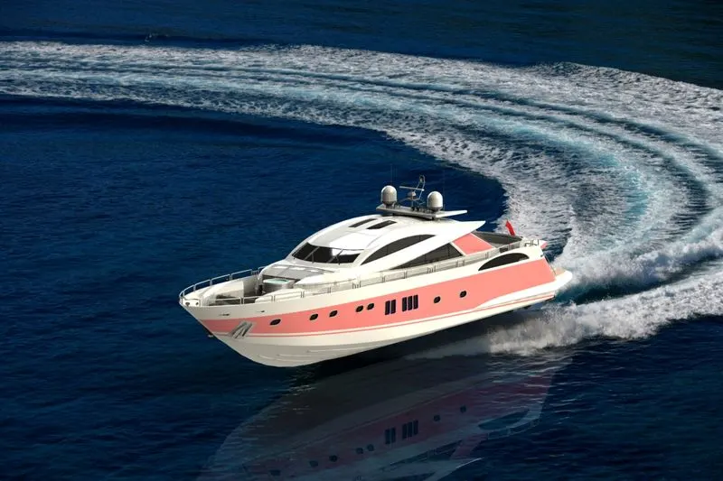
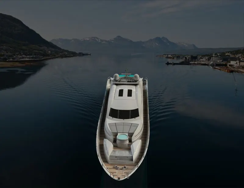
Solidworks visualize:The solidworks visualize provides a suit of stand alone software tool that combine indesterial oriented rendering capabilities with visualize design oriented features for work flow allowing easy and fast creation of visual content that communicates a design vision passion and emotion.
CONCLUSION:
- The parts of yacht are modelled by using various various tools available in solidworks.
- The modelled parts are assembled in assembly workbench by using mates.
- The assembled parts are rendered using photoview 360 and solidworks visualize.