Advanced Sheet Metal Design Using NX Cad Challenge_6_Bracket
Title: Metal Bracket
Objective: Designing a sheet metal Bracket using NX CAD tool
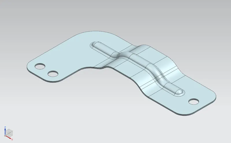
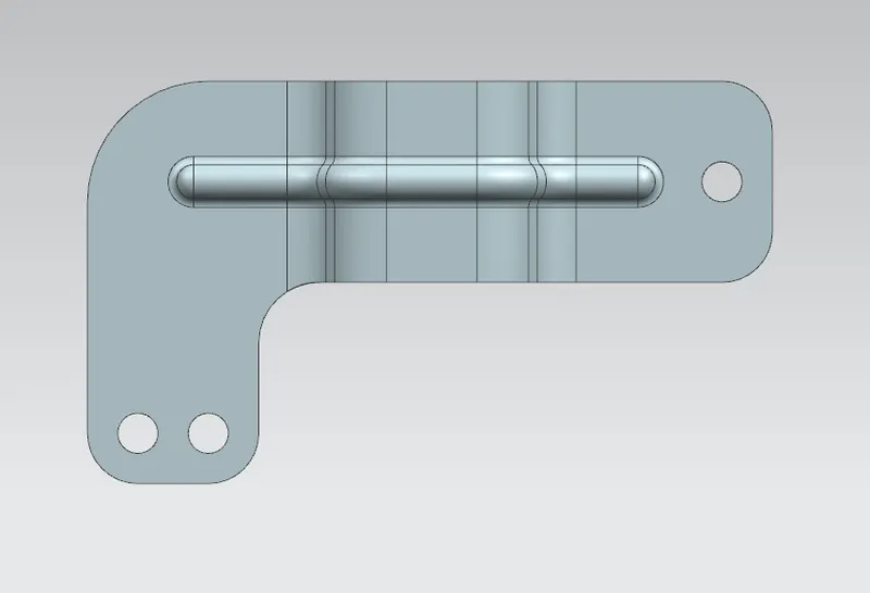
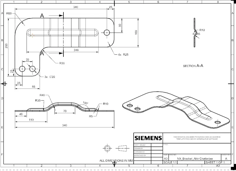
Introduction: This is a metal bracket which is L in shape with holes and a bead.
Design Methodology:
Base sketch is drawn> Creation of contour flange> Sketch of removal section> Removal of the corresponding section> Removal of sharp corners> sketch is drawn as path of Bead> Unbending of part> Creation of Bead> Re-bending of part> Creation of Holes.
Description:
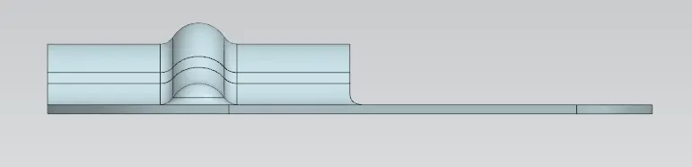
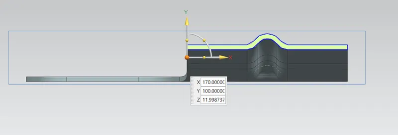
Base sketch of a hat section is sketched. Then it is made into 3D using Contour flange command. Again a rectangular sketch is drawn as removal section and is removed using Normal Cutout command. All sharp corners are removed using Break Corner command. A sketch of a line is drawn as a path for the upcoming bead. Unbending of part is done using Unbend command. Bead is placed in position using Bead command. Re-bending of part is done using Rebend command. Now, sketch is drawn to fix the position for holes. Hole command is used to create the holes.

Conclusion:
Hence, above sheet metal Bracket has been design with minimum possible operations.