Advanced Sheet Metal Design Using NX Cad Challenge_2_Box Assembly
Title: Box Assembly
Objective: Designing a sheet metal Box Assembly using NX CAD tool
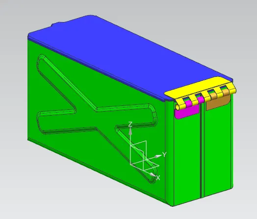
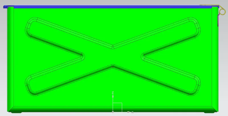
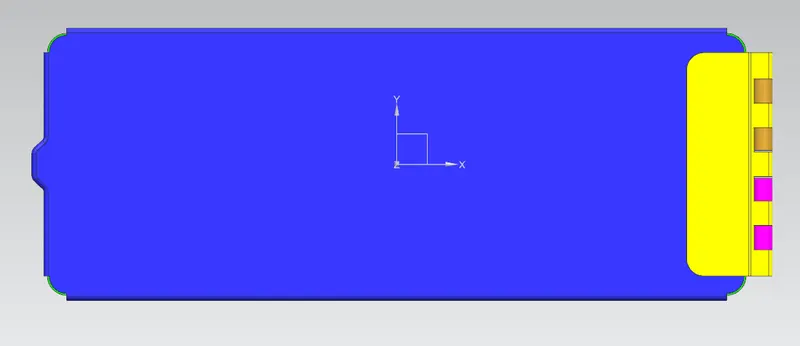
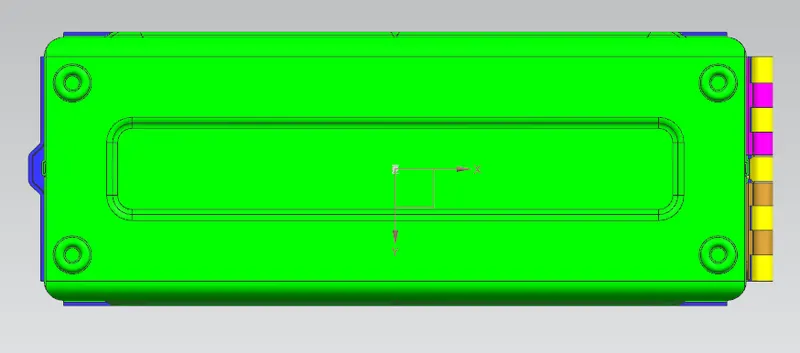
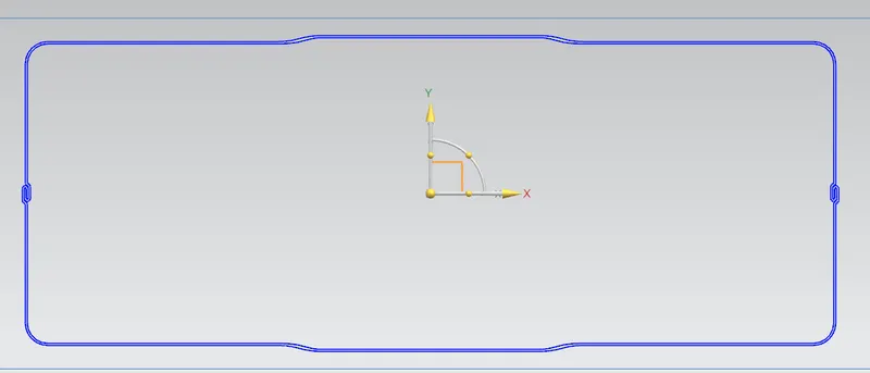
Introduction: This corresponding part is a sheet metal Box Assembly which has been designed with NX CAD tool. The Box Assembly consists of 5 parts i.e., the Box, the Lid, LH Hinge, RH Hinge and Lid Hinge. Stiffeners are provided in form of ‘X’ and Rectangular shape. Blank shape is also developed.
Design Methodology:
BOX: Creation of Tab > Creation of Flange on both length side > Creation of Flanges on width side LH and RH > Closing of corners at bottom on LH and RH sides > Creation of Flanges to form ‘Z’ shape on extremities of LH and RH Flange> Creation of Hem on extremities of LH and RH Flange> Mirroring of the part> Creation of Dimple in ‘X’ shape on length wall, Qty.02> Creation of Dimple in Rectangular shape on base> Unbending of part > Re-bend of part > Creation of Beads at bottom, Qty. 04> Creation of Hem near entrance of both Length side and Hinge side.
LID: Creation of Tab> Creation of Flange on LH side> Creation of Joggle on LH side> Creation of Flange on other 3 sides.
LH HINGE: Creation of Tab> Breaking of corners> Creation of Flange to form ‘Z’ shape> Creation of Hem> Unbending of part> Rectangular section is removed> Re-bend of part.
RH HINGE: Mirror of LH Hinge
LID HINGE: Creation of Tab> Breaking of Corners> Creation of Flange, approximately at 39 deg> Creation of Hem> Unbending of part> Removal of Rectangular section> Re-bend of part.
Flat pattern / Blank shape are developed for each part separately.
Description:
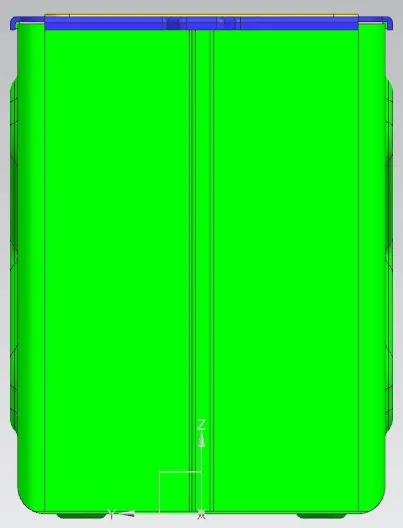
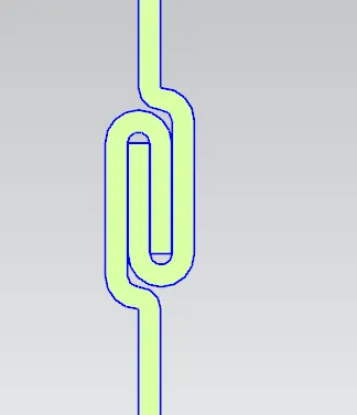
Most of the features are based on external sketches so that shapes and dimensions are parametric. The stock thickness is 1mm (as mentioned). The modelling starts by considering just half of the part i.e., on the plus side of the Datum Coordinate. First, base of 200 x 150mm has been created using Tab command. Flange on length side of 200mm depth is created using Flange command. Flange on width side of 70mm is created, both LH and RH, using Flange command. The bottom area on width side is closed by Close Corner command. On the width side, LH extremity, a fillet is created on outer edge by Flange command, using Bending Radius as 0mm and Length as 0.02mm. Then again flange is created using Flange command, this time Bend Radius as 0.5mm and Length as 6.5mm. Hence, creating ‘Z’ shape or a step. Same is created on RH extremity as well. Then Hem of type Open is created on both the extremities by using Hem command. Hence, creating an interlocking joint. Now the part is mirrored to YZ plane by using Mirror Body command. And both the bodies are joined to form a single body using Unite command. A stiffener of ‘X’ shape, placed horizontally, is provided on both the length wall using Dimple command. One more stiffener of rectangular shape of 320x50mm is provided on the base of the box. Then, unbending and rebending of part is done by using Unbend and Rebend command respectively. A bead of diameter 15mm are provided at the bottom of the part which act as stiffener and also as resting stand. It is done using Bead command. Mirror Feature command is used to mirror the beads with XZ and YZ plane. The quantities of bead are four. Creation of Hem, of type Close, near entrance of both length side and hinge side is done using Hem command. This is done for safe handling of the box.
Now, for creation of Lid, a Datum is taken parallel to XY plane at a distance of 203mm using Datum Plane command. A tab is created by Tab command. In this the dimensions are taken from the edges of the box using Project Curve command in Sketcher and modified accordingly. Creation of Flange on LH side of the tab using Flange command is carried out. Along this a joggle of Depth 7mm and Runout of 10mm is done using Joggle command. Joggle is provided as housing for the interlocking Hems. Flange command is again used to create flange on both length side of the lid. After this Contour Flange command is used to create flange on the hinge side.
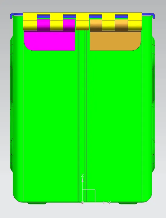
For creating the LH hinge, attached to the box, a tab is created using Tab command. Break Corner command is used to remove the sharp corner. Flange is made at an angle of 40 degree using Flange command. This same command is again used to make next flange with same angle. Now, a hem of type Open Loop with Bend Radius of 5mm is added using Hem command. Unbending of part is done. Sketch of 14x14mm is drawn and then removed using Normal Cutout and then re-bend using Rebend command. The RH hinge is created by mirroring the LH hinge with XZ plane, using Mirror Body command.
For making Lid Hinge, a tab of 128x36mm is created using Tab command. Break Corner command is used to remove the sharp corner. Flange is made at an angle of 39 degree using Flange command. A hem of type Open Loop with Bend Radius of 5mm is made using Hem command. Unbending of part is done. Sketch of 14x14mm is drawn and then removed using Normal Cutout and then re-bend of part is done using Rebend command. Flat pattern of all the parts are created by Flat Pattern command. The drawings are also been attached.
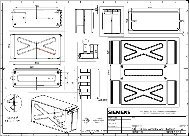
Conclusion:
Hence, above sheet metal Box Assembly has been design with minimum possible operations.