Advanced Sheet Metal Design Using NX Cad Challenge_1_Casing Design
Title: Casing Design
Objective: Designing a sheet metal Casing using NX CAD tool
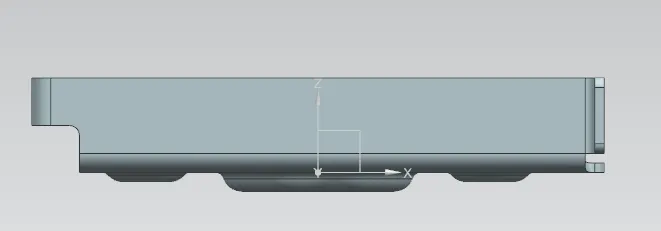
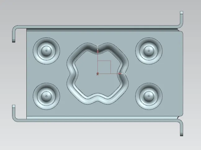
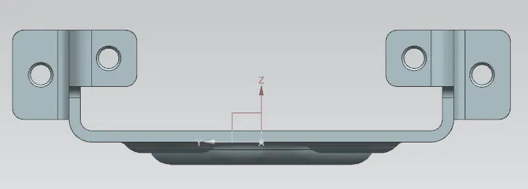
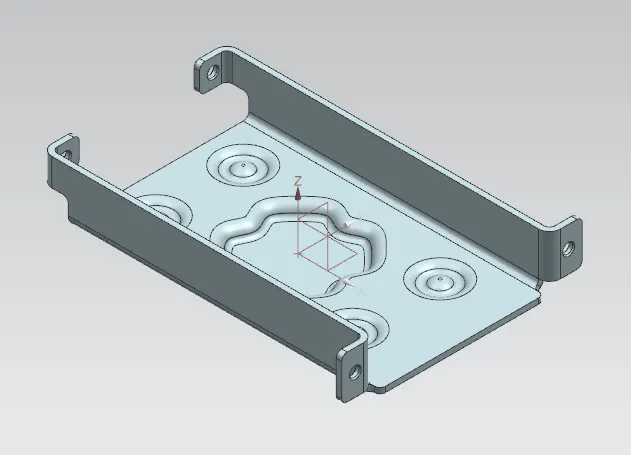
Introduction: This corresponding part is a sheet metal Casing which has been designed with NX CAD tool. The Casing consists of two primary flanges, two inner and two outer flanges for resting and screwing. It also consists of stiffness increasing feature such as Bead and Dimple. All Sharp edges are removed. Blank shape is also developed.
Design Methodology:
Creation of Tab > Rectangular section cutting > Creation of Flange on both length side > Creation of Inner Flanges > Creation of Outer Flanges with reliefs > Unbending of part > Creation of screwing Holes > Creation of Dimple at centre of the part > Creation of Beads, Qty.04 > Re-bend of part > Creation of Flat Pattern / Blank shape.
Description:
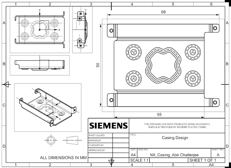
All the features are based on external sketches so that shapes and dimensions are parametric. The stock thickness is 1mm (as mentioned). First, base of 60 x 50mm has been created using Tab command. A rectangular section of 40 x 5mm has been removed by using Normal Cutout. Bends on both side of 10mm is created with Bend command which is followed by creation inner and outer flanges using Flange command where length of flanges are 5mm (as recommended). Here, Break corner command is used to remove all sharp edges for easy handling purpose and also relief from any stress concentration. Unbending of part using Unbend command, one flange at a time, in a sequence, till the part becomes flat. Creation / Positioning of screw holes using Hole command where hole is of M1.6 and fit is Normal (H13). The recommended value was M2 but due to its high proximity to the flange’s bend, it is modified. Creation of sketch for Dimple where Studio Spline and Move command has been significantly used. Finally, Dimple is created with depth of 1mm using Dimple command and followed by creation of Bead using Bead command of same depth and radius 1mm. The diameter of bead is 5mm and initial distance from XY coordinate is 7mm. Mirror Feature command is used to create another 3 Beads. These features are given as stiffener. Now, the part came to is original shape by using Rebend command. At last, Flat Pattern command is used to flat the entire part and get the blank shape and other details. The drawings are also been attached.
Conclusion:
Hence, above sheet metal Casing has been design with minimum possible operations.