Advanced Sheet Metal Design Using NX Cad Challenge_6_Bracket
DESIGN OF BRACKET COMPONENT USING NX SHEET METAL
OBJECTIVE:
To design and model the sheet metal bracket in Siemens NX cad sheetmetal software
INTODUCTION:-
- SIEMENS NX:- NX formerly known as "unigraphics", is an advanced high-end CAD/CAM/CAE, which has been owned since 2007 by Siemens PLM Software.
- SHEET METAL DESIGN:- NX Sheet Metal Design provides the design professional with a complete set of tools to efficiently create and manage sheet metal parts based on the knowledge of material properties and manufacturing processes. NX Sheet Metal Design tools incorporate material and bending information, enabling the model to represent both the formed component and flattened blank shapes
DESIGN METHODOLOGY:-
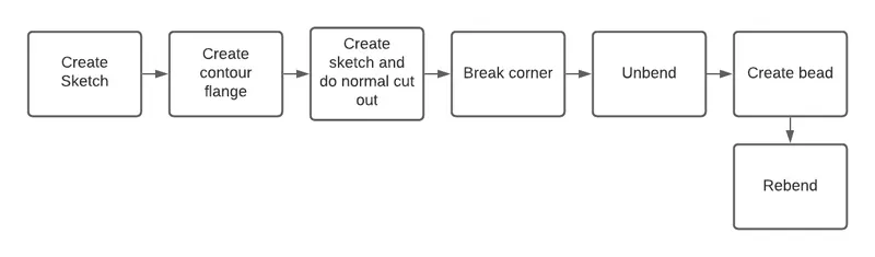
TOOLS USED
1.SKETCH :-
A Sketch is a named set of 2D curves and points located on a specified plane or path.You can apply rules, in the form of geometric and dimensional constraints, to establish the criteria your design needs.Features created from a sketch are associated with it, if the sketch changes so do the features
2.Datum plane:- It creates a datum plane used to construct other features. It is created to form the lid.
3.Datum coordinate system:- It creates a datum coordinate system used to construct other features. It is created as a reference to mirror the bodies and the features
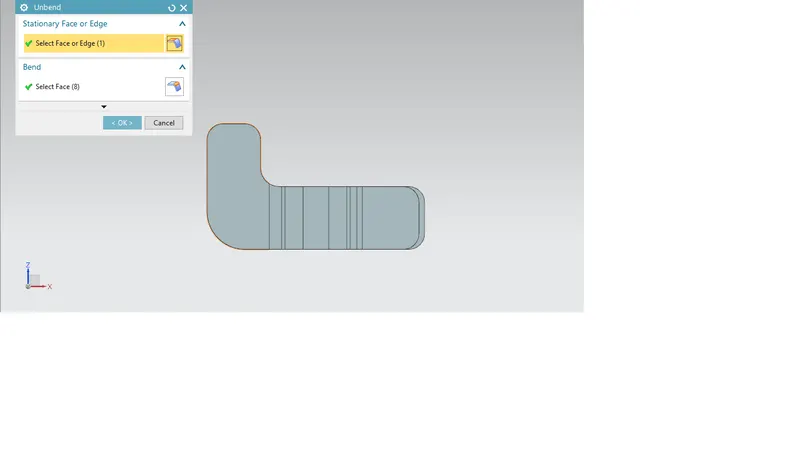
4.UNBEND:-
This feature is used to unbent the sheet metal taking any one face as a stationary face.
Flattens sheet model through selected bends.
To activate command:
- Click on command on (When sheet metal application activated.) “ Home => Form down arrow => Unbend”
- Activate command from “Menu => Insert => Form=> Unbend”
For Using “Unbend” command:
- Activate the “Unbend” command.
- Select the stationary face of the sheet metal.
- Select edges to bend
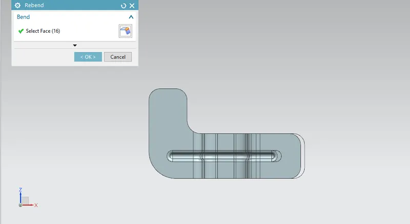
5.REBEND:- Rebends, the unbent feature of the sheet metal model.
It uses after the “Unbend” command If needed.
To activate command:
- Click command on (When sheet metal application activated.) “ Home => Form Gallery => Rebend”
- Activate command from “Menu => Insert => Form=> Rebend
- Select unbent faces on the model. (“Select Face” in the “Bend” tab highlighted automatically when command activated.)
- If you want to define stationary face on sheet metal model, click down arrow in the command window to open more options. Click on “Select Face or Edge“ in the “Stationery Face or Edge” tab in the command window. The function will be highlighted. Select stationary face on the model.
- Click the “Ok” to finish
6.BEAD:- Used for giving strength to the sheet metals
Bead command to lift material along the contour of a sketch that simulates a stamping tool. Beads can also be created to stiffen sheet metal parts.
- Choose Weld Assistant tab→Sealer group→Bead.
The Bead dialog box opens.
- In the Type group, Ellipse is selected.
- In the Primary Parts group, Select Face is active.
- Select a face on the primary part.
- In the Secondary Parts group, click Select Face and in the graphics window, select a face on the secondary part.
- In the Path group, click Select Curve or Point and in the graphics window select the curve you want to sweep the cross section along.
- In the Parameters group, set the parameters for defining the cross section.
- Click OK to create the Beadfeature
7.Flat pattern:- It creates a flat pattern feature from the formed sheet metal part. Separate flat patterns are created for the box, lid and the hinges.
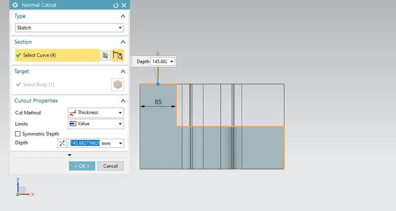
8.Normal Cutout:- Normal Cutout command to cut material by projecting a sketch onto the model and then cutting perpendicular to the faces intersected by the projection.
You can use planar sketches or 3D curves to specify the section for the normal cutout. If the sheet metal part has multiple bodies, you can specify the target body on which you want to create the normal cutout
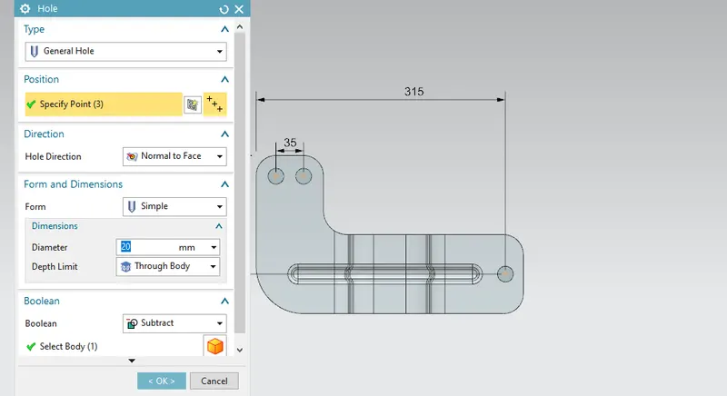
9.Hole :- Hole command isto add the following types of hole features in a part or assembly
- General holes (simple, counterbored, countersunk, or tapered form)
- Drill Size holes
- Screw Clearance holes (simple, counterbored, or countersunk form)
- Threaded holes
- Holes on non-planar faces
- Holes through multiple solids as a single feature
- Multiple holes as a single feature
DESCRIPTION:-
- Sketch is created on the XY plane
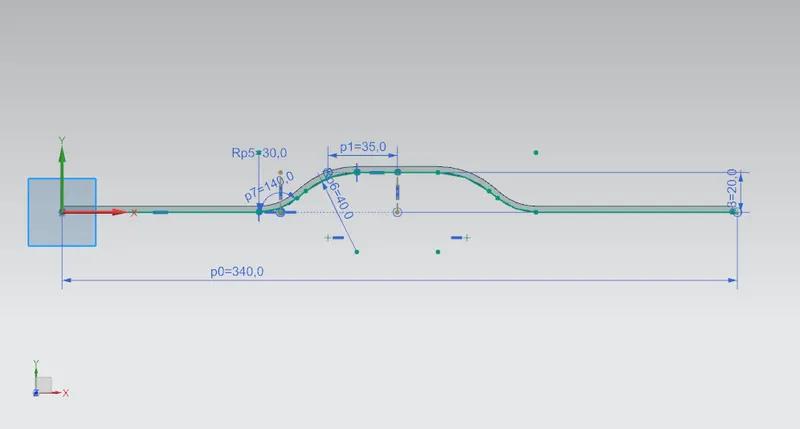
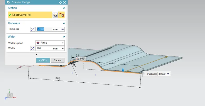
- Use the contour flange command and select the sketch as shown below,determine the thickness as 3mm for the flange.
- The skecth is required to use the normal cutout feature. So, we are creating sketch in XY Plane
- Break corner command is used on the corners of the bracket
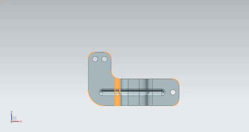
- The braket is unbended to create the bead
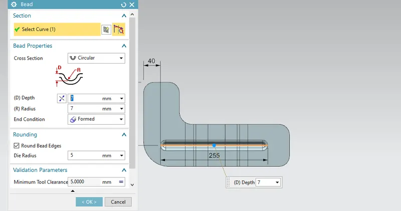
- After doing bead the braket is rebend to the original position
- Holes are created using hole command on the bracket
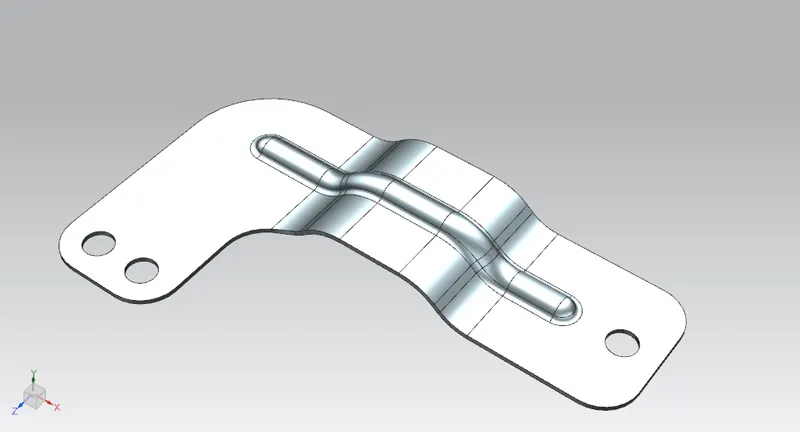
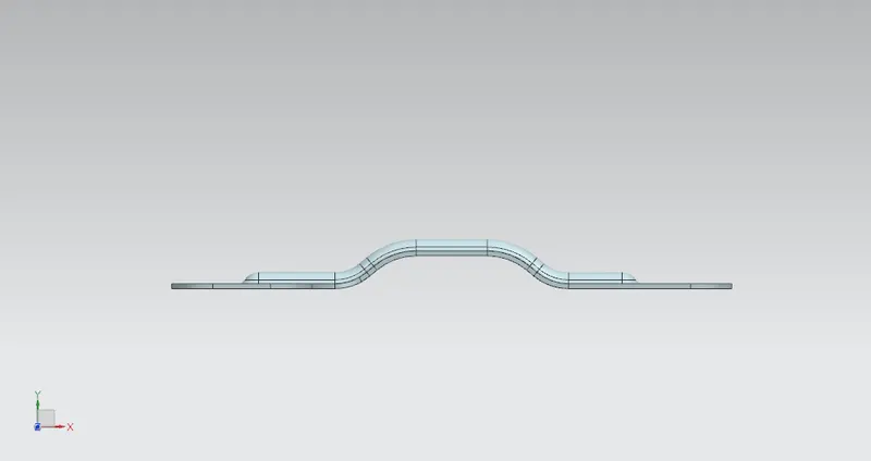
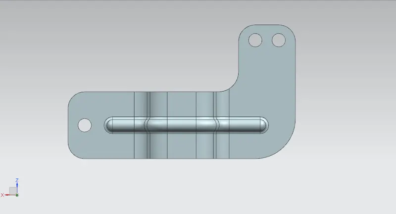
STANDARD VIEWS OF THE BRACKET
FRONT VIEW
TOP VIEW
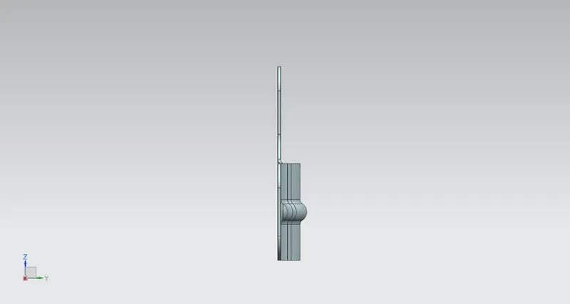
SIDE VIEW
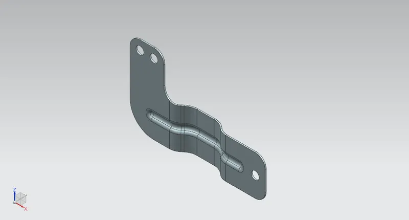
ISOMETRIC VIEW
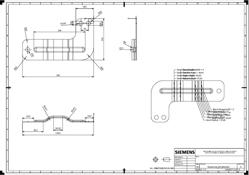
DRAFTING IMAGE
CONCLUSION:
The sheet metal Recommended workflow to create Bracket Component or angles is successfully completed in NX Cad.