Advanced Sheet Metal Design Using NX Cad Challenge_5_Odd Shaped Enclosure
Odd Shaped Enclosure
Objective: To create an Odd Shaped Enclosure using NX CAD and write a detailed report on Sheet Metal Component with good explanation on Sheet Metal modelling tools applied throughout the modelling.
Design Methodology:
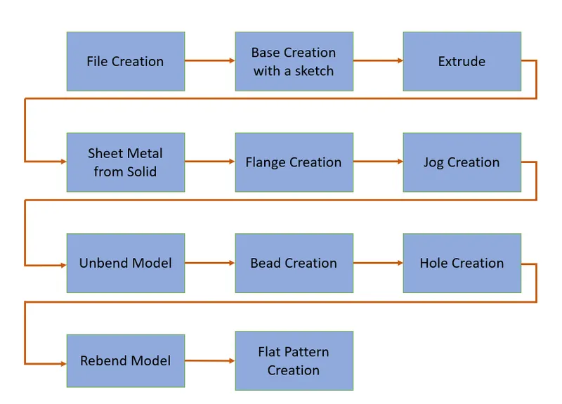
Description:
The commands that were used for the creation of this model are given below,
1. Extrude: This command is used to extrude the material in the given direction based on a sketch. This is used to create the main body in this challenge.
2. Sheet Metal from Solid: This is sheet metal applciation command that is used to convert a solid body, for example, the body created using the extrude command in this challenge, into a sheet metal body so that unbent and rebent with the addition of extra features and a flat pattern can be obtained from it. The sheet metal from solid command also gives the user the ability to rip the edges of a solid body so that it can properly mimic a sheet metal component.
3. Flange: It is used for the creation of the required flanges in the model. In this model we use it to create the protrusion on one side.
4. Jog: It is used for the creation of flanges with bends in the model. This can be observed on the opposite side of the flange in this particular model.
5. Unbend: This command is for the purpose of making the created structure a flat body by opening up all its bent areas.
6. Hole: As the name suggests, it's purpose is for the creation of holes on the surface of the model.
7. Bead: The bead command is used for the creation of bead features on the surface of the model.
8. Rebend: It is used to counteract the unbend command after the creation of the extra features on the surface, to obtain the original and intended shape of the model.
9. Flat Pattern: The flat pattern command is used to obtain a the model as an 2D engineering sketch with all the required dimensions of choice.
Various Views of the Model
Shown below are the various images that depict the different views of the model created:
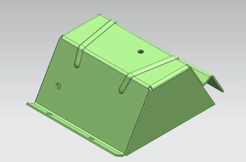
Isometric View
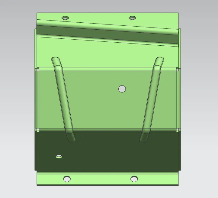
Top View
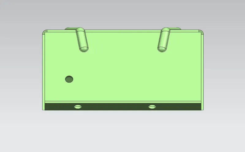
Front View
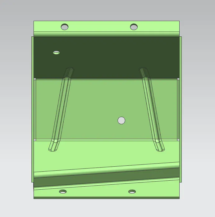
Bottom View
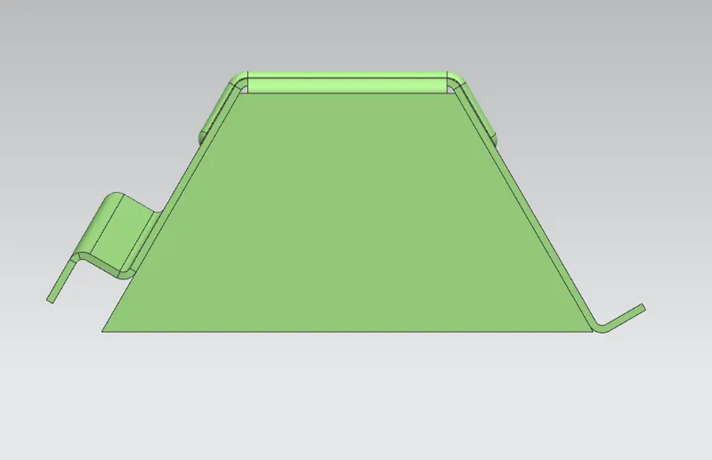
Side View
Flat Pattern:
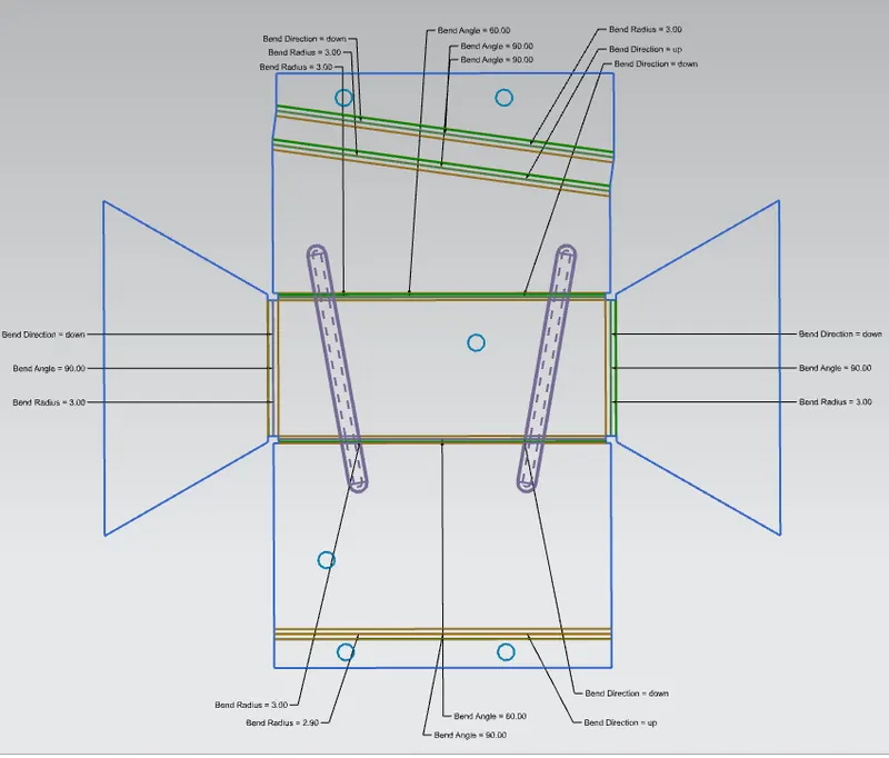
The flat pattern command is used to create 2D engineering sketch of the sheet metal model that was created. It can contain all the dimensions and various other parameters which are required to convey the information to someone else, for example the Bend Radius, Bend Direction and the Bend Angle can be depicted if needed. The image below shows the flat pattern of model that was designed in this challenge and for better scrutiny, the flat pattern can be observed in the model that is attached.
Conclusion:
The model was created as per the design requirements and the flat pattern of this very model was also created.