Advanced Sheet Metal Design Using NX Cad Challenge_5_Odd Shaped Enclosure
TITLE: Odd Shaped enclosure using NX CAD.
OBJECTIVE: To design an odd shaped enclosure using NX CAD tool
INTRODUCTION:
Sheet metal is metal formed by an industrial process into thin, flat pieces. Sheet metal is one of the fundamental forms used in metal working and it can be cut and bent into a variety of shapes.
Sheet metal is available in flat pieces or coiled strips.Parts manufactured from sheet metal must maintain a uniform thickness for ideal results.
There are many different metals that can be made into sheet metal, such as aluminium, brass, copper, steel, tin, nickel and titanium. For decorative uses, some important sheet metals include silver, gold, and platinum.
Sheet metal is used in automobile and truck (lorry) bodies, airplane fuselages and wings, medical tables, roofs for buildings (architecture), and many other applications.
DESIGN METHODOLOGY:
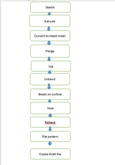
DESCRIPTION:
STEP1:
Start NX CAD,then set the global parameters.
STEP2:
Design a base sketch to form a solid profile and extrude it.
EXTRUDE: It is a method of defining three dimensional geometry bt translating a 2D sketch normal to the sketch plane
STEP 3:
Convert it into sheet metal using sheet metal from solid.
SHEET METAL FROM SOLID: It is used to convert the solid profile into sheet metal.
STEP 4:
After forming it to the sheet metal,add flange & jog to form a profile.
FLANGE: It creates a flat bended profile at an angle to a planar face.
JOG: It is used to create the flange by lifting the material on one side of the sketch line drawn.
STEP 5:
After creating flange,unbend the profile with the use of unbend option.
UNBEND: It is used to flatten the bended profile.
STEP 6:
Create the sketch for creating beads,then select bead option with circular cross section and give proper radius and depth.
BEAD: It is used to lift the material along the contour of the sketch.
STEP 7:
Sketch six reference points for holes on profile which was unbend before,then create holes with their respective hole size and fit.
HOLE: It is used to create the hole on the model which is used for assembling and mounting.
STEP 8:
Finally rebend the model to get the bended view of the model
REBEND: It is used to restore the model to its bended state.
STEP 9:
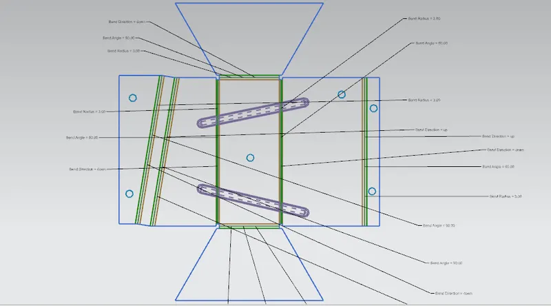
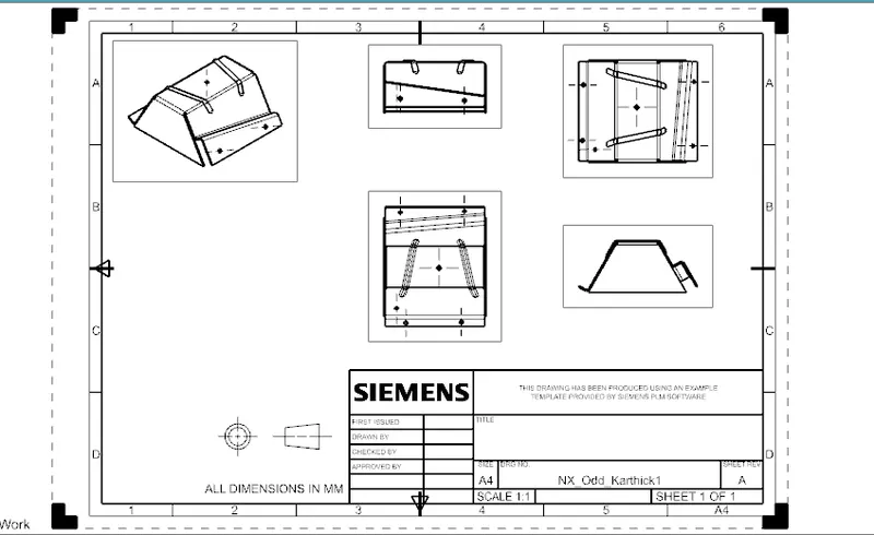
After rebending create a flat pattern view of the model for drafting purpose.
FLAT PATTERN: It is used to create the flat pattern view which is used for drafting purpose.
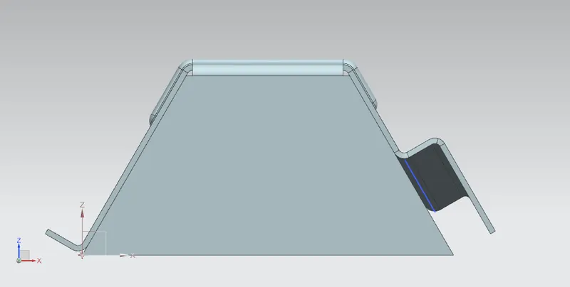
FRONT VIEW:
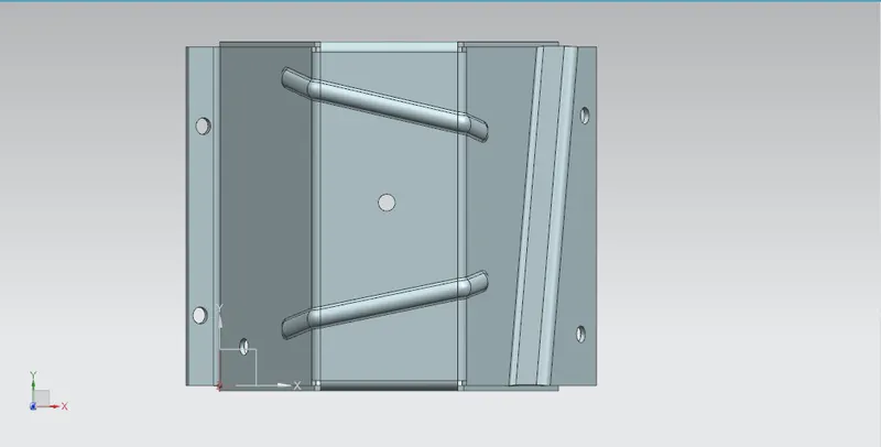
TOP VIEW:
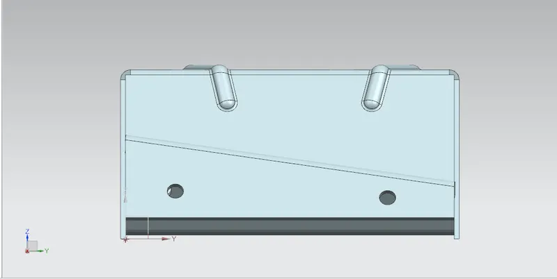
RIGHT SIDE VIEW:
ISOMETRIC VIEW: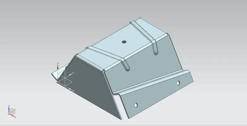
FLAT PATTERN VIEW:
DRAWING SHEET:
CONCLUSION:
Thus the Odd shaped enclosure has been designed with the use of NX CAD tool and learned about feature involving in creating the sheet metal model.