Advanced Sheet Metal Design Using NX Cad Challenge_6_Bracket
DESIGNING A BRACKET USING SHEET METAL IN SEIMENS NX CAD
OBJECTIVE:
- To design a Bracket using the NX Sheet Metal.
- To learn about tools and feature used while designing the Sheet Metal Bracket.
INTRODUCTION:
Sheet metal is used in various platforms in manufacturing industries. Sheet metal is metal made by the industries to make thin, flat piece. In NX CAD sheet metal application is used in Machineries, Automobile industries, Aerospace industries, etc. It is made up of Steel, Aluminium, Copper, Brass, Tin, Nickel, etc. It comes with a foil rolled along itself. Sheet metal enclosures is use to resist corrosion and provide electrical conductivity. The product is widely used for various industrial purposes. The brackets are made by the use of metal stampers. The metal brackets are used to maintain hole alignment and provide strength to the model in automobile industries. The brackets are also used to provide a rigidity to overhanging objects. In western countries this metal bracket is used to protect a house from the tornado. Here I have designed a simple metal bracket design.
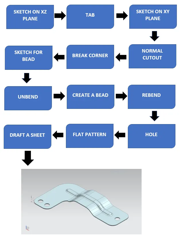
DESIGN METHODOLOGY:
DESCRIPTION:
- SKETCH: This is used as a primary feature for any type of modelling.
- CONTOUR FLANGE: By using this command we can add a flat flange to the model at a required angle.
- NORMAL CUTOUT: This command is used to remove the material from a model. The cut made by using this feature will be perpendicular to the face.
- BREAK CORNER: This command is used to create a smooth corners to the edges.
- UNBEND: This command is used to unbend the sheet metal to perform deferent operations which can be operated using unbend feature only.
- BEAD: This command is used to lifts the material along the contour of the sketch that simulates the stamping tool.
- REBEND: After finishing all these operation the sheet metal parts need to rebend to its previous bend state. After rebending we can see that all the operation we have performed after unbend feature. They can now also been seen without any change in the parameters.
- SIMPLE HOLE: This feature is used to create a throughout hole on the sheet metal in this exercise we have used this after unbending.
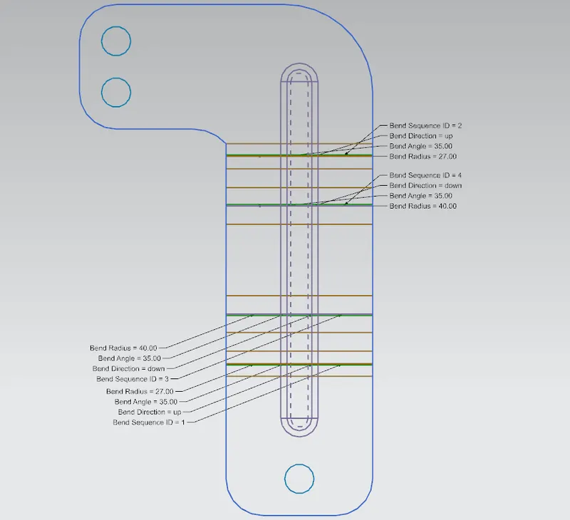
- FLAT PATTERN: This feature is used to create a 2D sketch on the sheet. The flattened model is necessary for the manufacturing process. This involved all the detailed dimensions required for manufacturing.
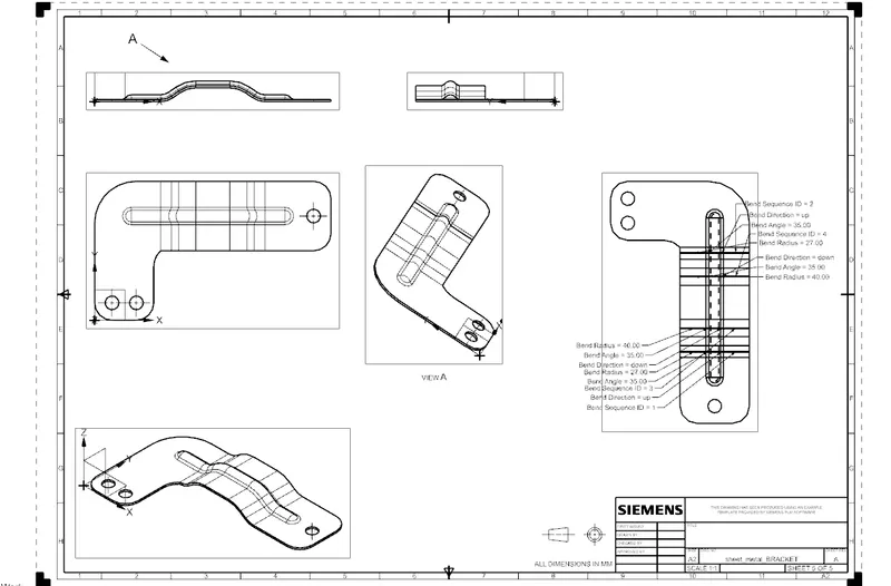
- DRAFTING: By using this feature we can easily create a Sheet that can be used for the manufacturing process.
PROCEDURE:
- To create a Bracket we first need to adjust a plane on datum coordinate system. Select the XZ and create a sketch using lines and circle.
- Now use contour flange feature and give the dimension of 200mm.
- Again create a new sketch on XY plane and use normal cut out feature.
- Use SB Break Corner to get smooth edges.
- Draw new sketch to create a bead feature.
- Now use Unbend feature and create a bead with Depth and Radius of 7mm each and Round bead radius of 5mm.
- Now rebend the model.
- Check for local radius option.
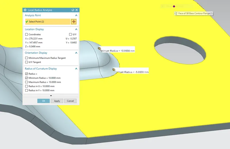
- Now create a new sketch for the use of hole feature.
- Now use measure distance option as guided.
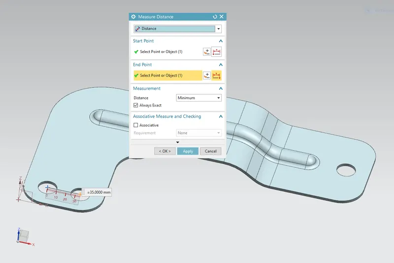
- Now we need to use flat pattern to get the detailed information’s regarding the sketch.
- Now at last draft the design and save the file.
ISOMETRIC VIEW:
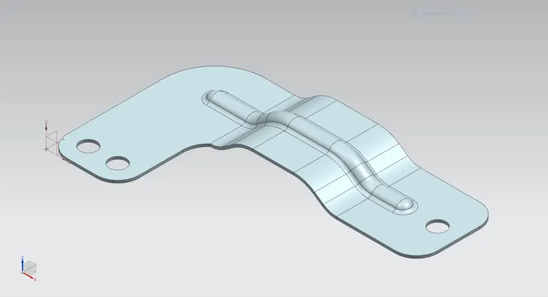
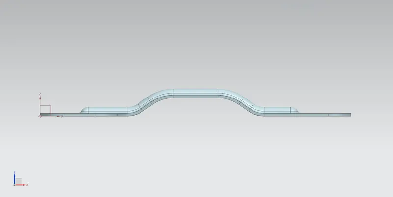
FRONT VIEW:
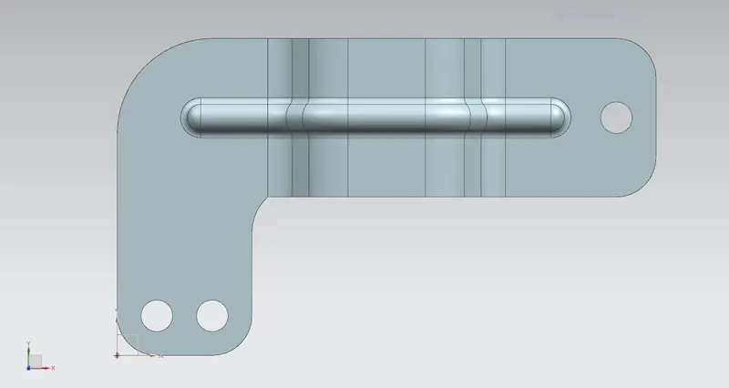
TOP VIEW:
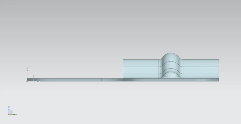
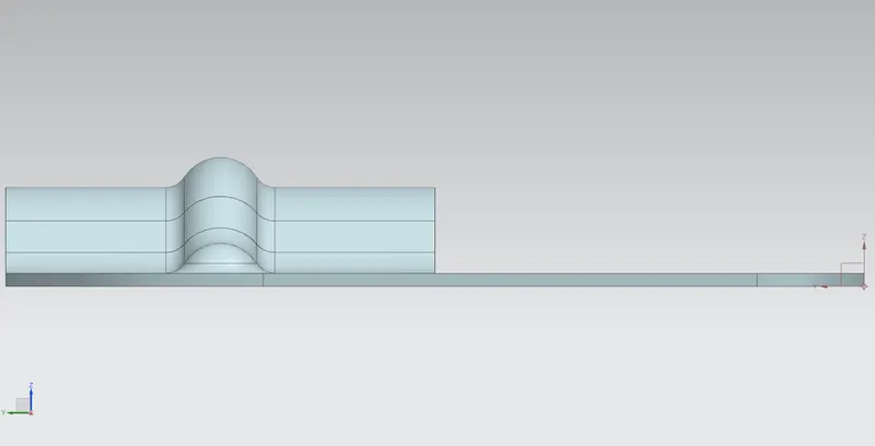
SIDE VIEW:
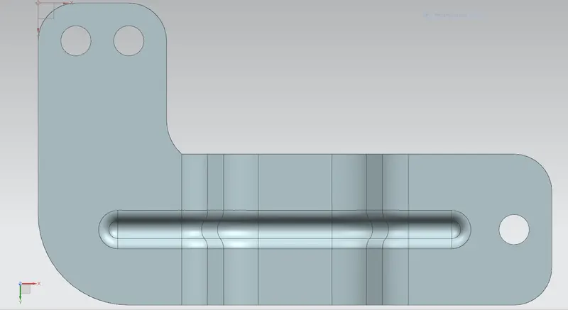
BOTTOM VIEW:
FLAT PATTERN VIEW:
DRAFTED SHEET:
CONCLUSION:
THANK YOU
NAME: AVINASH LANJEWAR