Advanced Sheet Metal Design Using NX Cad Challenge_2_Box Assembly
- Title of the Project :
Advanced Sheet Metal Design Using NX Cad Challenge 2 Box Casing
- Objective: To make a 3D model of Sheet metal in NX of Box Casing Assembly
- Introduction : We make sheet metal design using NX CAD of Box Casing Assembly
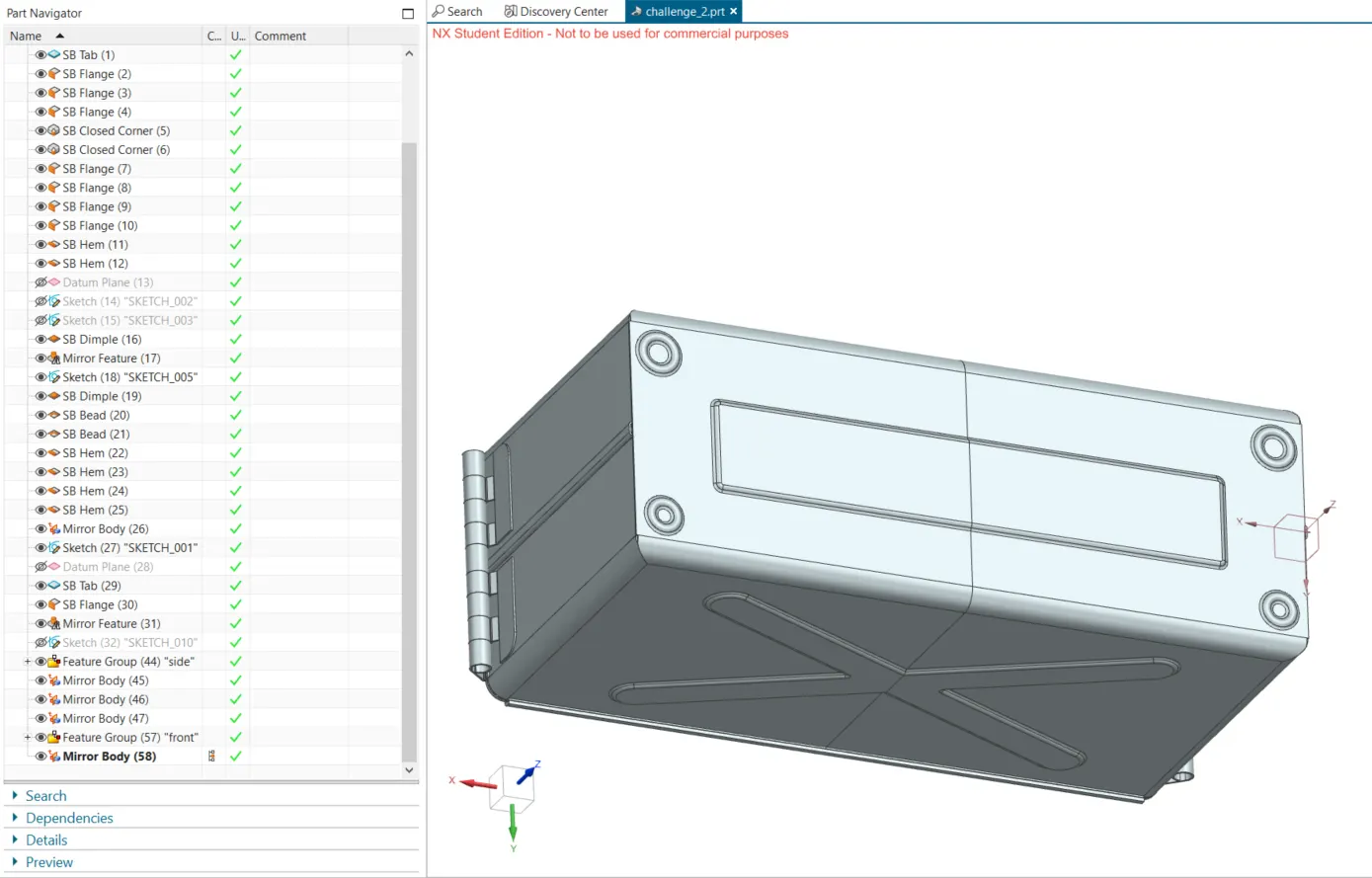
- Design methodology : We use many tools in this sheet metal design, to generate the final sheet metal body. this is done step by step given in the following steps.
- Description :
1. A base is created using tab command. this is the bottom surface.
2. flanges area created on 3 sides using the flabge command.
3. then corners are closed using close corner command from both the sides.
4. then flange woth bend radious 0 and length 0.02 are drawn on both sides.
5. hem is drawn twice to lock these flanges.
6. features are mirrored on the Y-Z plane.
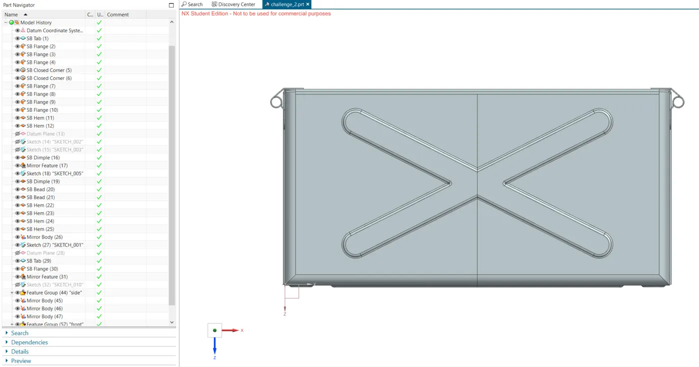
7. dimple command is used to draw dimple on the large surface, which is then mirrored.
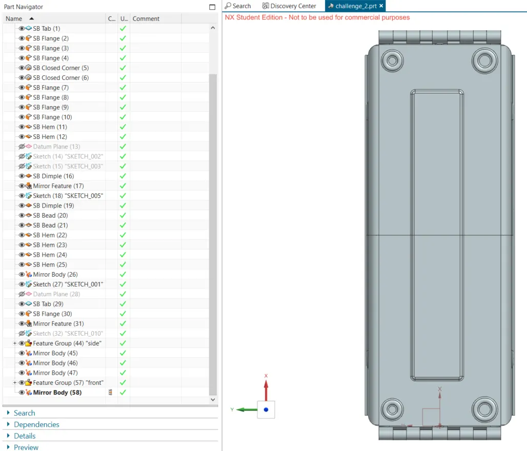
8. another dimple is drawn on the bottom surface.
9. four beads are drawn on this surface then.
10. then hems are drawn on the boundary surfaces.
11. then lid is drawn using the tab command.
12. flanges are drawn to it to cover on the sides.
13. a tab si drawn on the side weall and break corner is used.
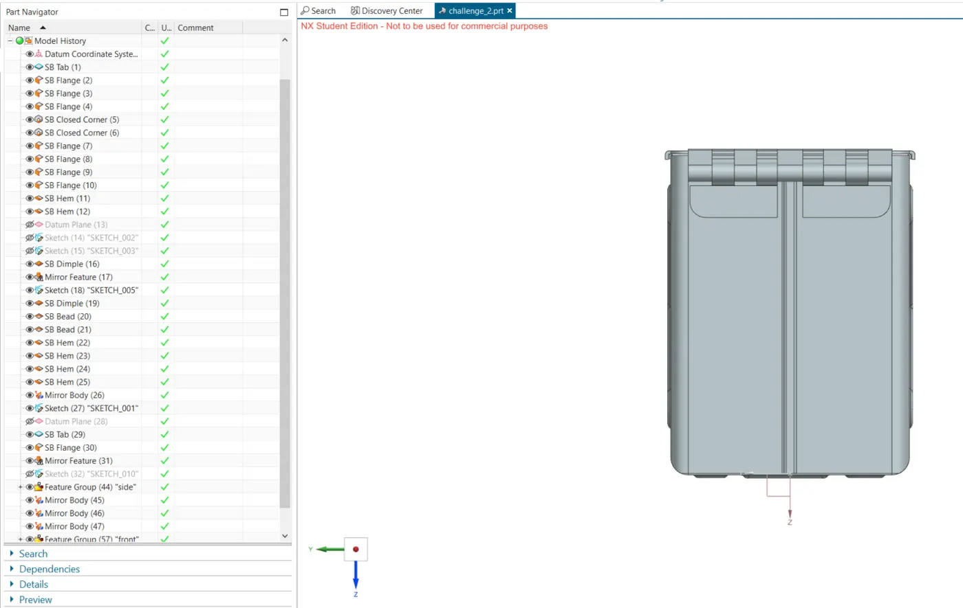
14. falnges and hem are drawn on this to simulate a handle figure.
15. unbend and rebend commands are used to successfully produce these using normal cutout.
16. these are mirrored to ahve four such structures.
17. drawing a tab feature on the top lid and using the same commands used to create the handle figure features. unlike what was done formerky, we now make a normal cutout figure to compensate the gaps between those handles.
18. this feature is mirrored again, to have reflect it on the opposite sides of the larger length of the casing box.
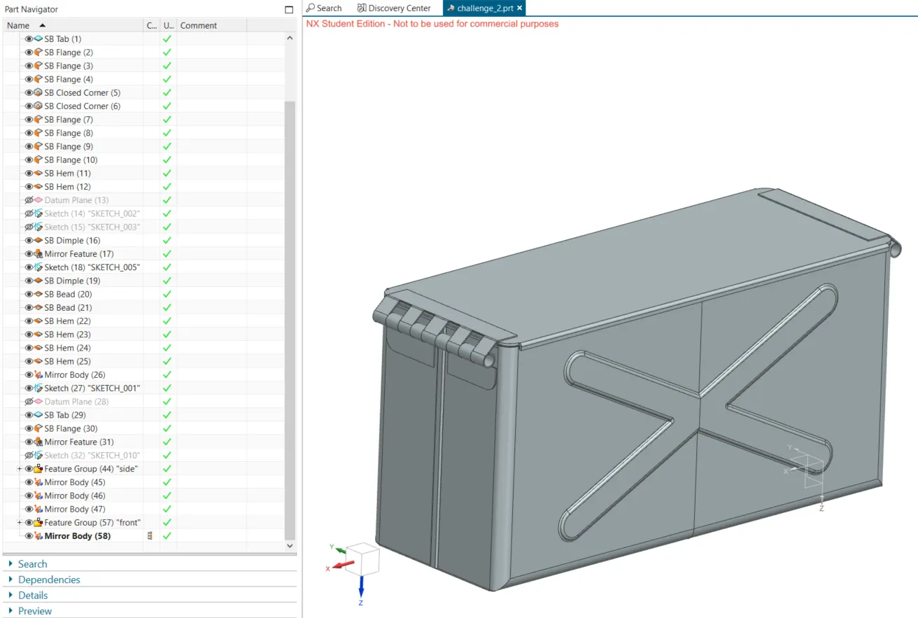
19. we have our final box casing ready.
7. Conclusion:
hence the sheet metal body box casing is made using NX sheet metal design.