Advanced Sheet Metal Design Using NX Cad Challenge_2_Box Assembly
Title of the Project :-
NX Box_Aseembly USING NX SHEET METAL COMMAND
OBJECTIVE:-
Creat sheet metal part "Nx_Box_Aseembly". This part design on sheet metal application with uniform thickness and proper bend radius.
Introduction
NX sheet metal design software incorporates material and process information in sheet metal-specific modeling features: bends, flanges, tabs, cutouts, beads, dimples, louvers, corner and edge treatments, patterns and other formable features. You can also quickly convert solid models to sheet metal components, and create sheet metal parts that enclose other components.
Design methodology:-
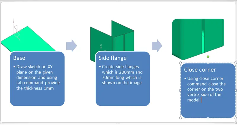
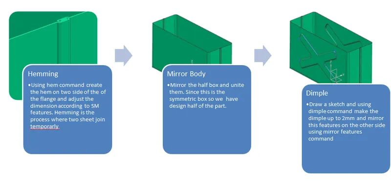
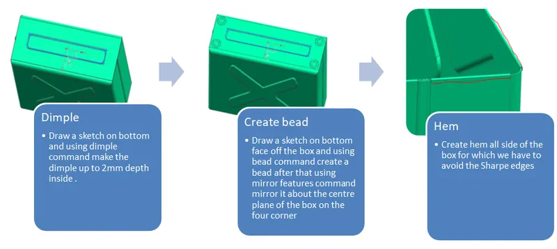
1. BOX DESIGN
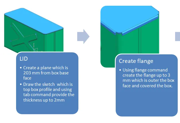
2. LID DESIGN
3. HINGES DESIGN
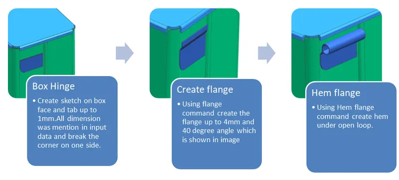
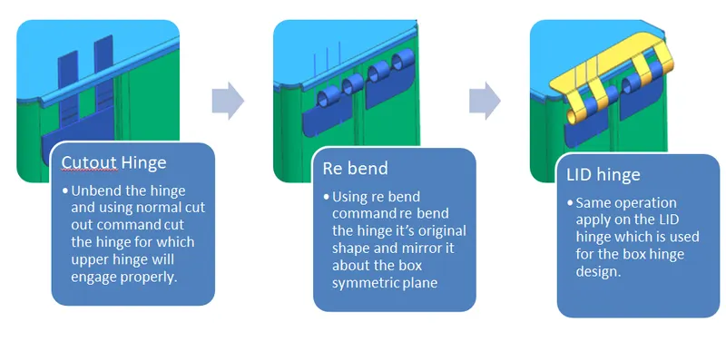
Description:-
Tools used in box design assembly
- Tab:- Using to make the base features
- Flange:- for creating side wall on the sheet metal part at any angle
- Closed Corner:- To close the corner of two bend area
- Hem Flange:- Creating hemming feature which is open or close in some particular fashion to avoid sharp edge
- Dimple:- Create draw features to provide the strength of the SM body.
- Bead: Create some support features on the SM part.
- Mirror Geometry. Copy the geometry
- Mirror Features:- Copy the features like bead,heam flang, etc
- Break corner: Provide radius or chamfer on corner
- Un bend: Flatten the SM part for apply some other feathers
- Re bend: Rebend the part to it's original design.
- Normal cut out: Removing some unwanted material from SM part.
ISOMETRIC VIEW
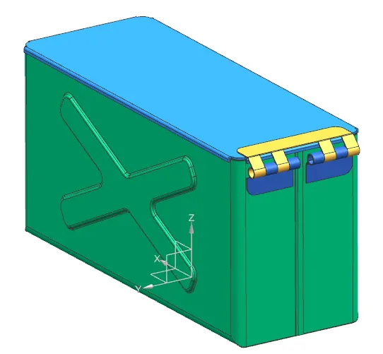
FRONT VIEW
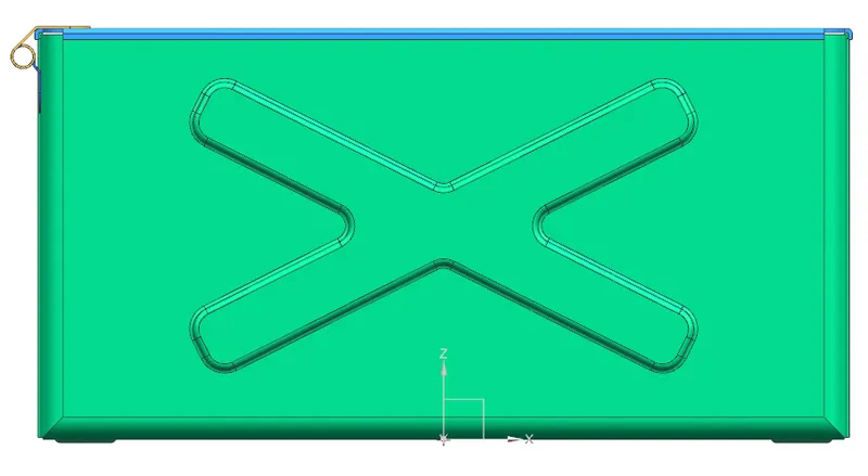
TOP VIEW
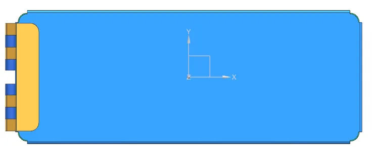
RIGHT SIDE VIEW
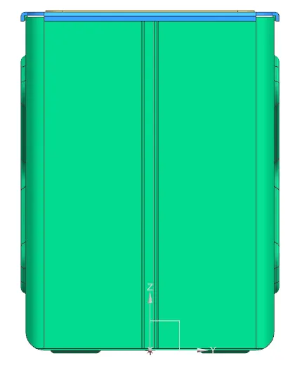
BOTTOM VIEW
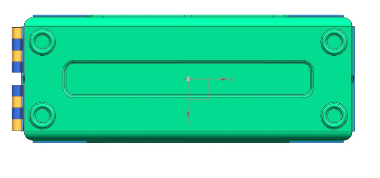
DRAWING VIEW
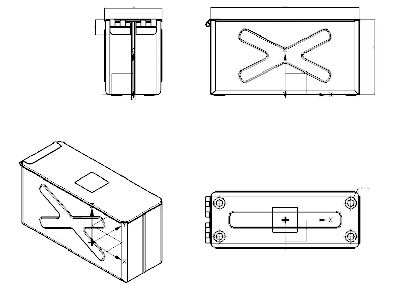
Conclusion
Box assembly design has been done and all the parts place in seperate features group in part modeling.