Advanced Sheet Metal Design Using NX Cad Challenge_2_Box Assembly
OBJECTIVE
Design a box assembly using NX Cad by following the design rules.
INTRODUCTION
Sheet Metal Fabrication is the process of forming parts from a metal sheet by punching, cutting, stamping, and bending.3D CAD files are converted into machine code, which controls a machine to precisely cut and form the sheets into the final part. Sheet metal parts are known for their durability, which makes them great for end use applications.
DESIGN METHODOLOGY
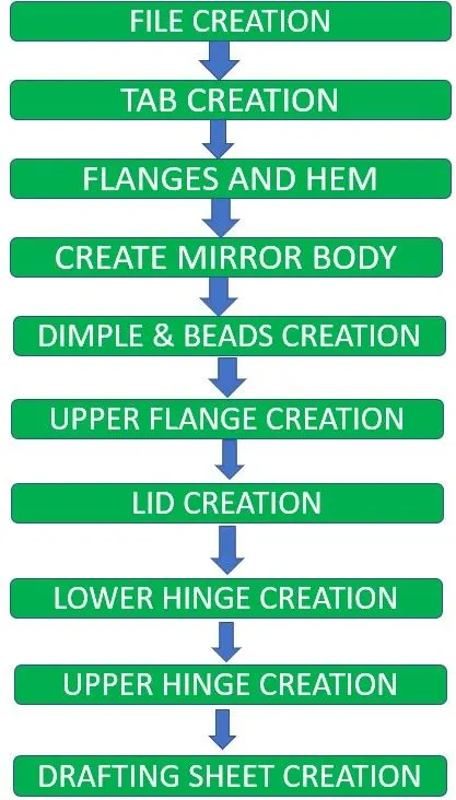
DESCRIPTION
File Creation:- Create a sheet metal design file in Nx Cad and name it.
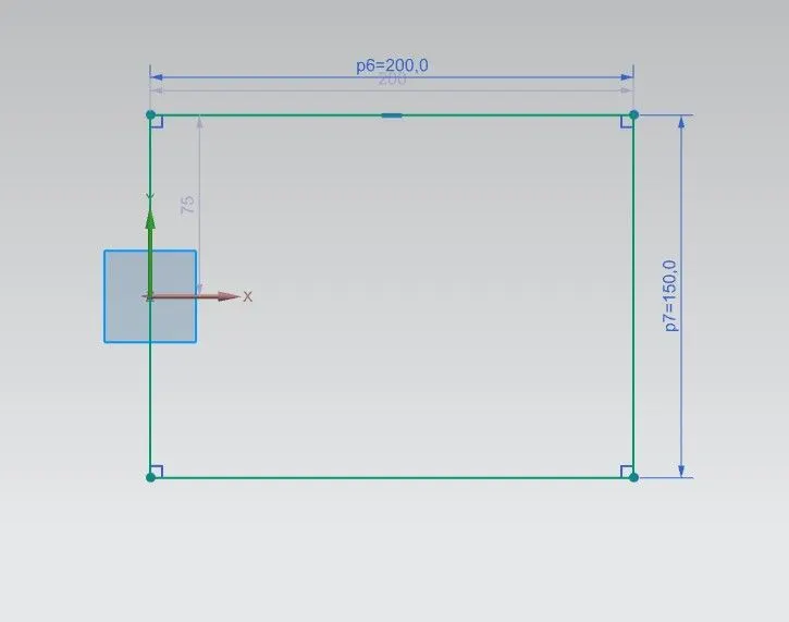
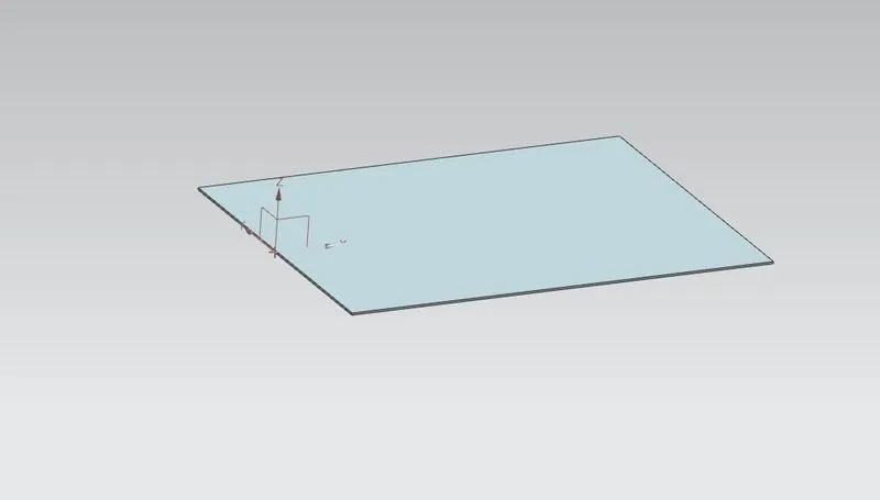
Tab Creation:- Create a rectangular sketch on XY plane of 200mm length and 150mm width after that use TAB command to create a Tab of that sketch.
Flanges and Hems Creation:- Create 2 flange of length 200mm on the top and Bottom of the tab. then create 2 flange of length 70mm on the first flange, then CLOSE the corner by using CLOSE CORNER command.
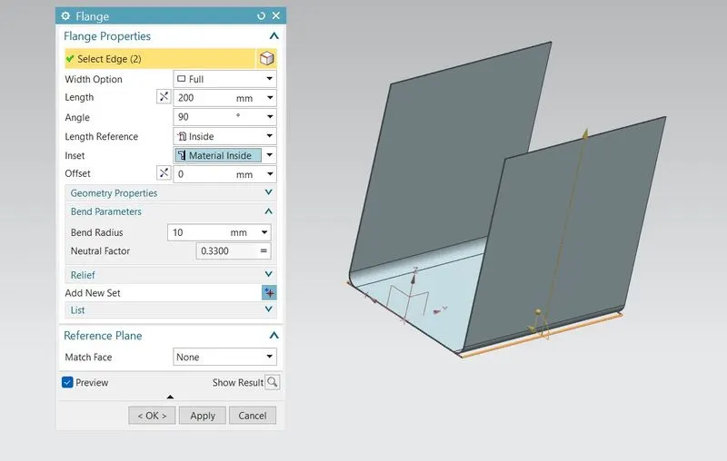
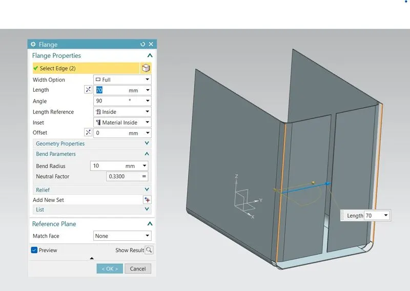
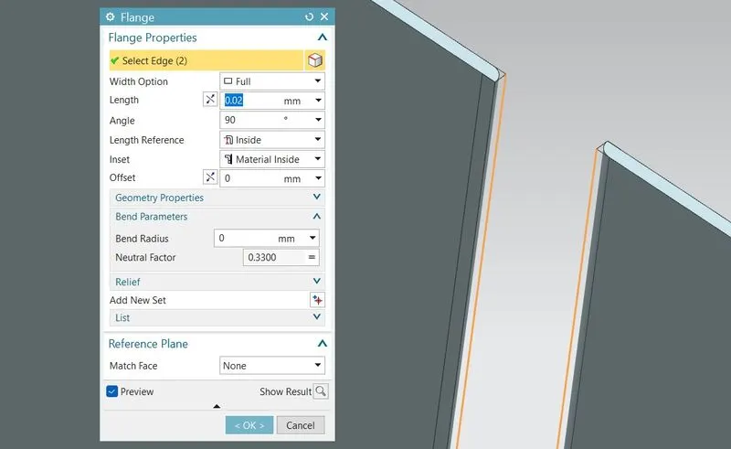
Create Open hems on the both flanges.
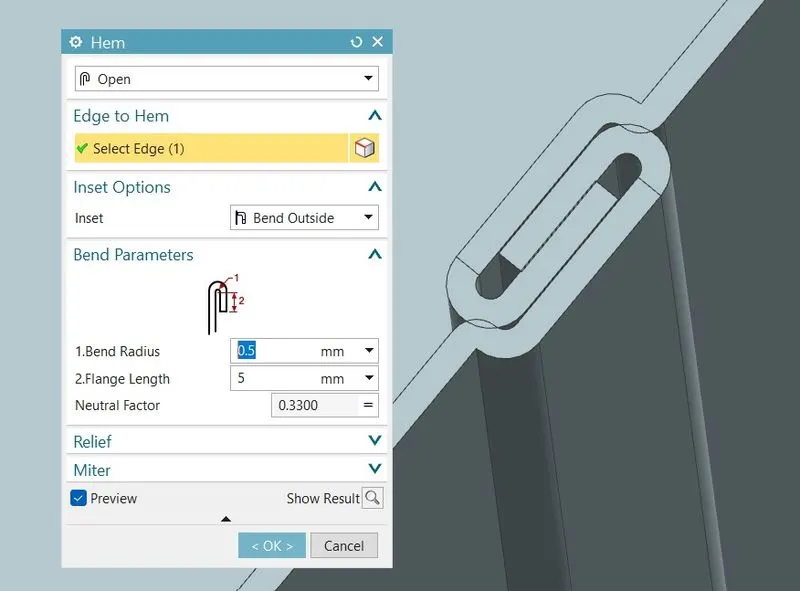
MIRROR BODY:- Use Mirror body command to create another half of the body by using the center plane after that use UNITE command to join both body.
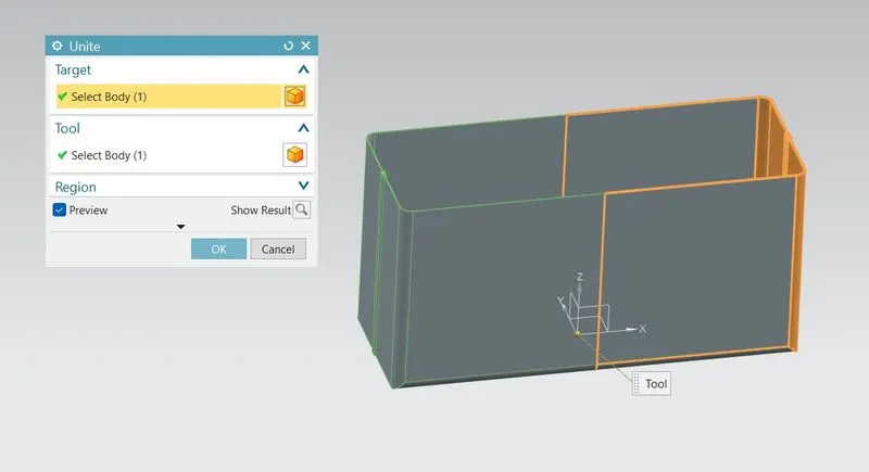
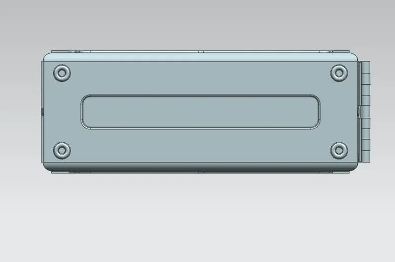
Dimple and Beads Creation:- Create the sketch for Dimple and beads, Then use DIMPLE and BEADS commands to make it. Depth of Dimple and Beads should be 2mm and the beads diameter is 15mm. Then use Mirror feature to create 4 beads on the 4 corners.
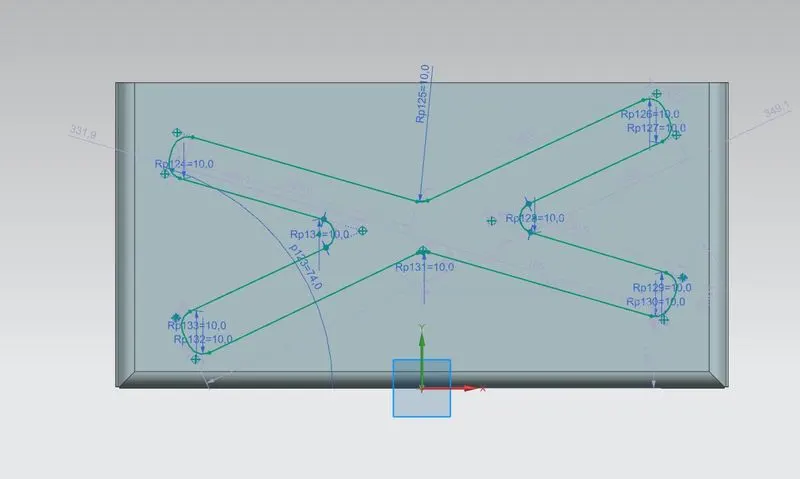
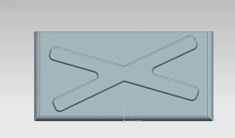
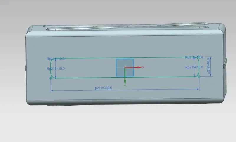
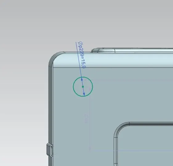
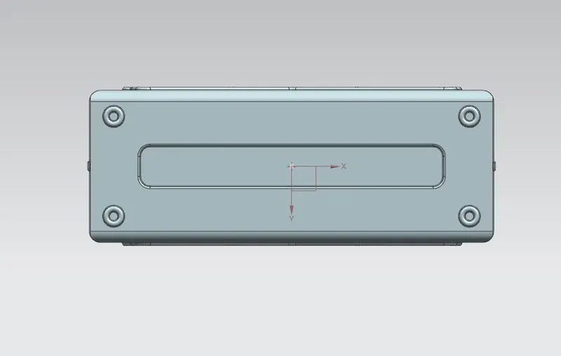
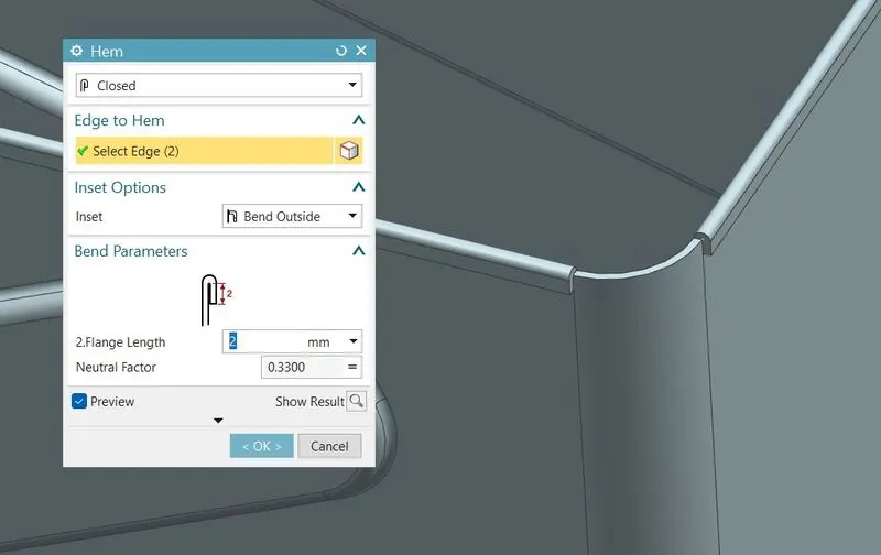
UPPER HEMS CREATION:- Create HEMS on the upper side on the model except the corners.
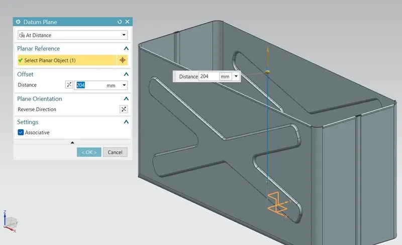
LID CREATION:- Create a which is offset at 204mm. Create sketch on that plane, according to the shape of the upper side then use TAB command to create a 2mm thick lid to cover the upper side then create flanges on the Lid.
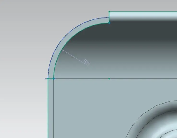
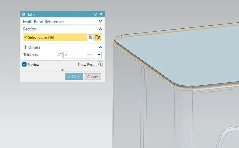
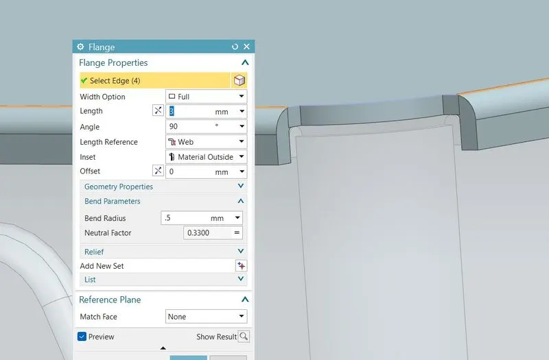
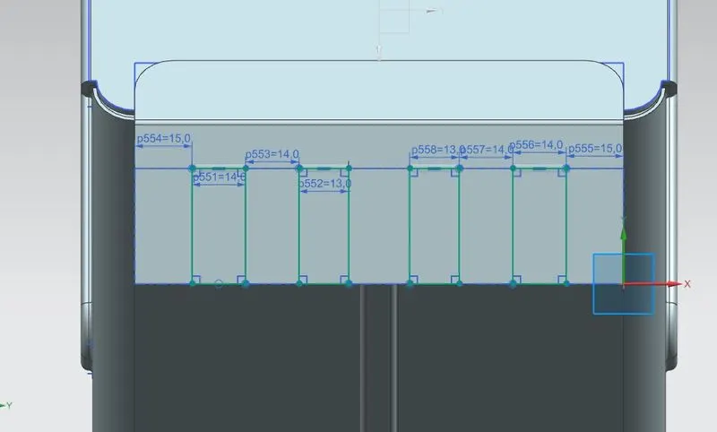
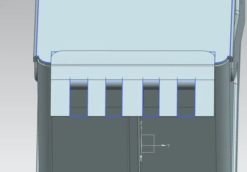
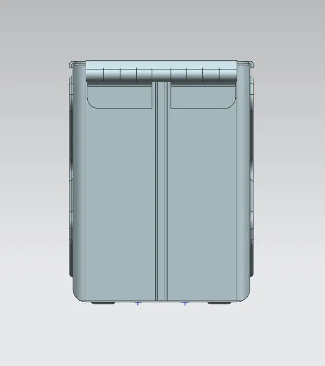
LOWER HINGE CREATION:- Create a Tab of 55mm length and 20mm height on the body then use break corner and create 2 flanges as shown in the below image then Use HEM command to bend at 5mm and 325 sweep angle. After that unbend it create a sketch for the cutout and Use NORMAL CUTOUT to cut it and again Rebend It By using REBEND command, then use MIRROR BODY command to create it at another side also.
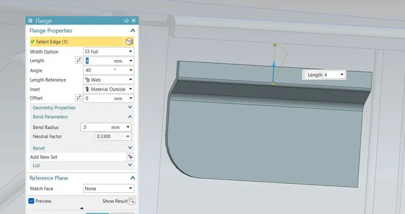
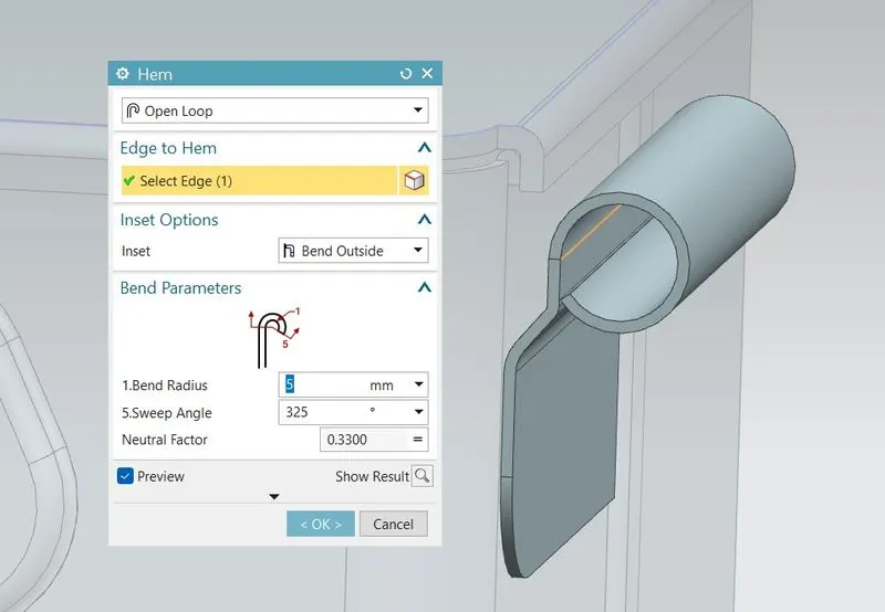
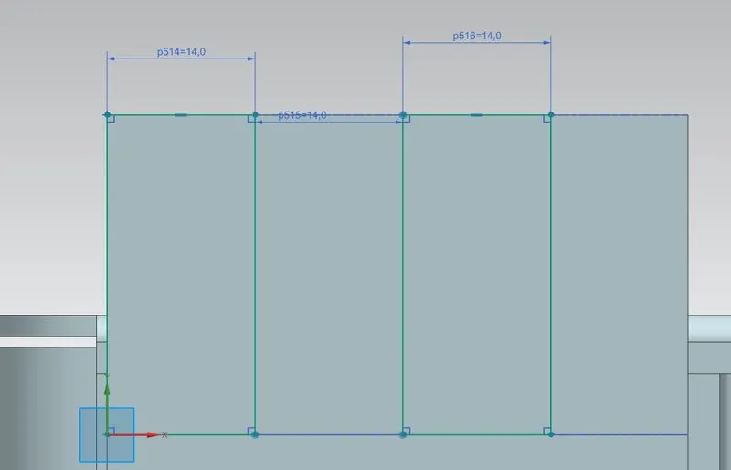
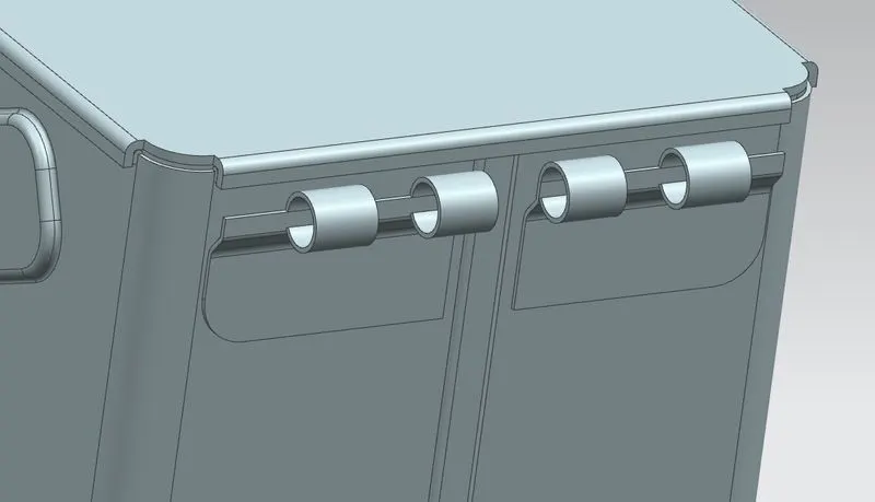
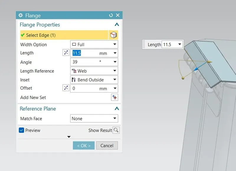
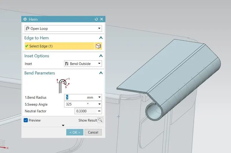
UPPER HINGE CREATION:- Create a rectangular tab of 55mm length and 20mm height on the top of the lid then use BREAKE CORNER command to smoothen the edges then create flange of 11.5mm and create HEM on the flange of 5mm radius and 325mm sweep angle then UNBEND it and create sketch for the cutout, then use NORMAL CUTOUT and REBEND command.
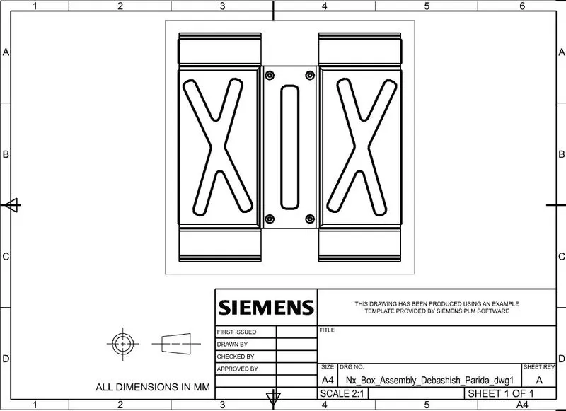
DRAWING SHEET IMAGE
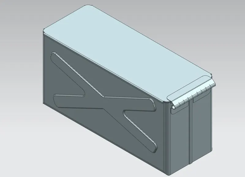
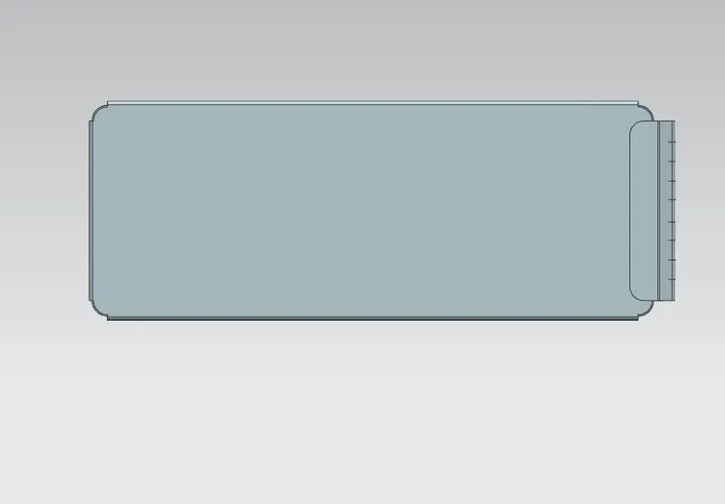
MODEL IMAGES
CONCLUSION
This design of Box Assembly model is created using nx cad by following the design rules.