Advanced Sheet Metal Design Using NX Cad Challenge_2_Box Assembly
MODELLING OF SHEET METAL BOX ASSEMBLY
AIM : To design a sheet metal box assembly using NX Cad software with suitable commands to achieve the final product as per the inputs.
INTRODUCTION :
Sheet Metal is a type of material that is flattened into thin sheets. Sheet metal is made by taking a large cast in and rolling it into a long ribbon of the thickness it wants. This flat metal is rolled into a coil and sent directly or cut the metal into sheets before being sent to a machine shop.
The sheets are made from metals such as aluminum, brass, copper, steel, tin, nickel, and titanium. The sheet’s thickness depends on the material needed for a project. Thicknesses can vary from 0.15 -6.00 mm significantly; extremely thin sheets are considered foil or leaf, and pieces thicker than 6 mm (0.25 in) are considered plate steel or “structural steel.”
Cutting :
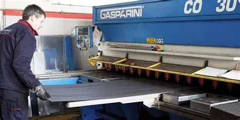
Sheet steel is cut by a shearing method that was used a lot before being replaced by faster and precise methods. A punch press is used to punch and die sets to cut the metal. It is effective for cutting simple parts which is then cut with a laser or a water jet.
It operates at hundreds of strokes per minute; a punch press makes suitable parts quickly. Punching is used to make holes or other cutouts in parts. The creation of a complex flat pattern with size-limited stamped features is done through laser cutting and combining punch.
Bending :
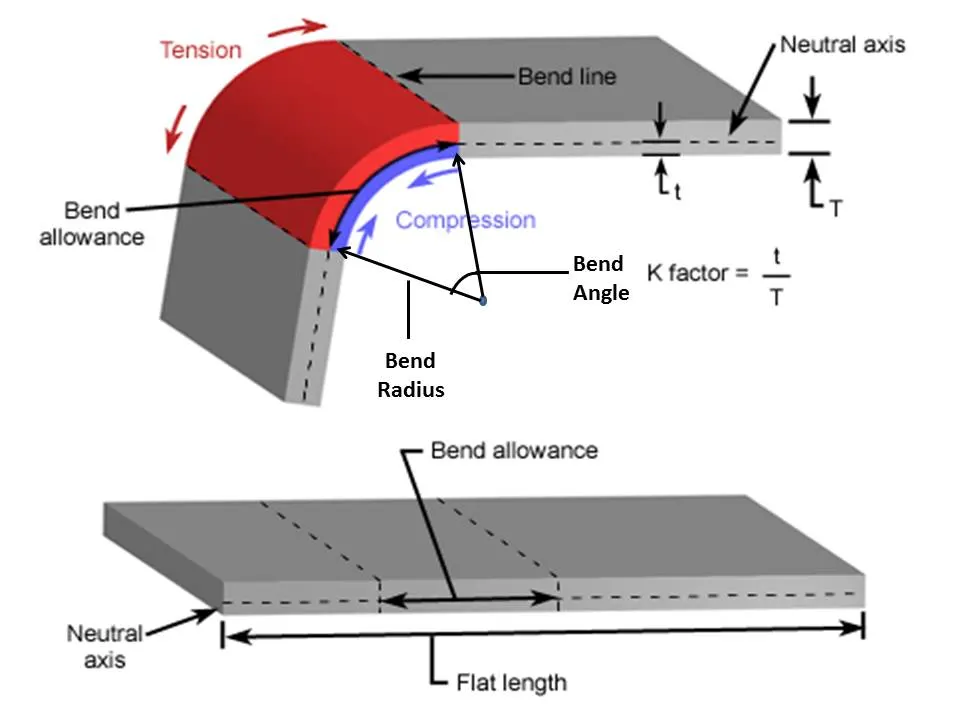
Some metals can be bent along a straight axis using a variety of presses. Bends shape can be varied from gentle curves to vertical axis of steel used to sharpen the corners at an angle above, below, or right at 90 degrees. Press brakes are used to create these sharp bends. Open or closed single-axis curves can be produced by the rolling and forming method in a bending operation.
Hemming :
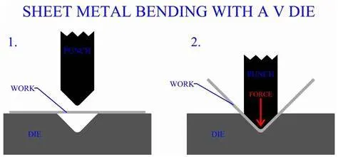
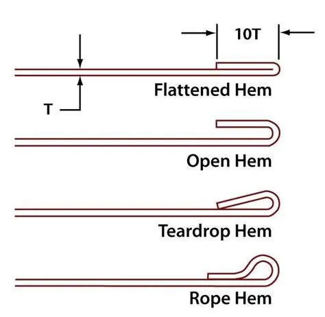
It is the rolling edge of a metal shape that provides a smoother, stronger edge that is open, leaving an air space with a bend or closing the folded metal that is pressed tightly against itself.
Barrel hem is the curling that produces a rounded edge to a piece of metal. It is used to eliminate the sharp edges or serve an operational function in the case of a door hinge that holds the pin around the hinge rotates.
Bend Radius :
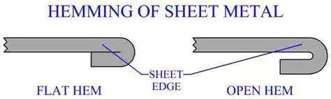
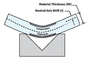
It is the inner radius of the sheet metal after bending .
K Factor :
The K-factor is the ratio of the neutral axis to the material thickness. When a piece of metal is being formed, the inner portion of the bend compresses while the outer portion expands . The neutral axis is the area of transition between compression and expansion, where no change in the material occurs—except that it moves from its original location at 50 percent of the material thickness toward the inside surface of the bend. The neutral axis does not change its length but instead relocates; this causes elongation to occur during bending. How far the neutral axis shifts depends on a given material’s physical properties, its thickness, inside bend radius, and the method of forming.
Design methodology IN Flowcharts
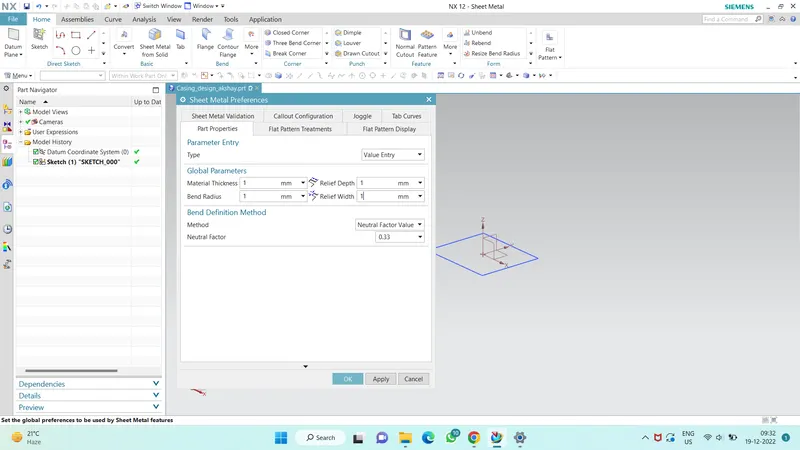
Select the XY Plane to draw the Sketch

The tab is created with Reference Sketch
Advanced flanges on the edges of bends create in the previous step
Bending operation is done on side of the tab behind the cut-out
on the tab created as a sketch to perform normal cut-out operation
Unbend the Sheetmetal by using unbend command
Added the holes were ever required by using the Hole command
Sketch is created on the Surface of tab to perform dimple operation
Studio Spline option is selected to create a spline curve
Rebend the Sheetmetal By using Rebend command
Beads also created with reference to holes where placed at required points Dimple operation with reference to Spline curve
Rotated Spline curve to 45 degree
final product was achieved as per the inputs
Final Touch up was given in Drafting Sheet with a suitable Scale
Commands are used in design :
- Sketch : It’s a basic command to draw 2d models.
- Tab : A command to add parameters of a Sketch
- Bend : It’s an operation to bend the tab at a particular position with reference
- Flange : It’s an operation to extend of a sheet metal with to one of the edge of an tab
- UNBEND : It’s a command used to flatten the created 3d model taking one face as a stationary face.
- HOLE : It’s a command used to create a different type of holes like tapping and normal drilling, on the Surface of an Sheet metal.
- DIMPLE : It is a projection command of a particular shape with reference to a sketch with a certain depth.
- BEAD : It is also the type of projection to deform the shape at a certain point with reference to sketch and also give strength to the material.
- HEM : Hem is used for bend the edges.
- Normal Cutout : For cutting the sheet metal it is used.
- REBEND : This command is used to re-bend the already flattened sheet metal.
- Mirror Body : This command help to mirror same part with the of plane for complete the part.
- Unite : This command is used for joining operation of two parts.
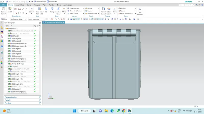
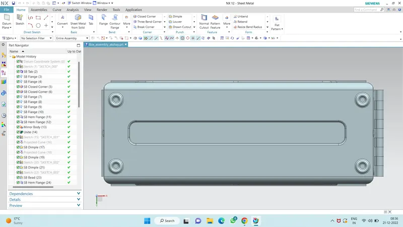
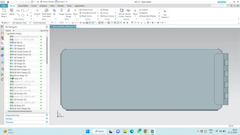
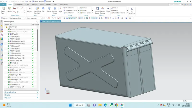
Different Views of Part after complete the design with the help of given PDF :
All Views :
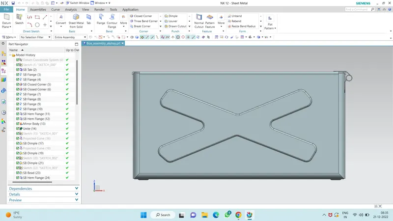
Isometric View :
Drwing Sheet :
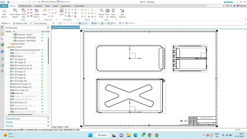
Part Navigator :
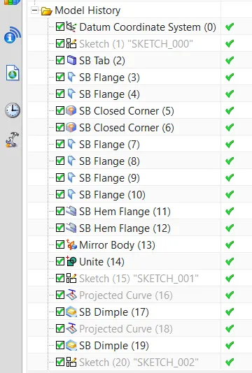
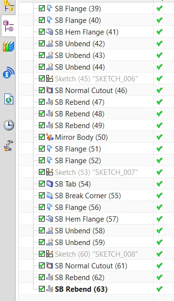
CONCLUSION :
Finally the modelling of the sheet metal Box Assembly using NX CAD has successfully completed and though this project I can able to know the various GUI of NX and different comments and tool use in various sheet metal modelling.