Advanced Sheet Metal Design Using NX Cad Challenge_2_Box Assembly
TItle : Advanced Sheet Metal Design Using NX Cad Challenge_2_Box Assembly
Objective : To create BOX ASSEMBLY - Advanced sheet metal designing using NX CAD
Introduction :
- Sheet metal is metal formed by an industrial process into thin, flat pieces. It is one of the fundamental forms used in metalworking and it can be cut, bent into a variety of shapes.
- Materials which can be made into sheet metal - Alluminium, copper, brass, steel, nickel, tin and titanium.
- Sheet metal used to design - Machinery
- Automobiles
- Airospace
- wings, Enclosures, brackets, etc.
DESIGN Methodology / Commands to be used :
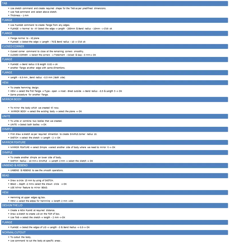
DESIGN PROCEDURE NX CAD :
1. TAB :
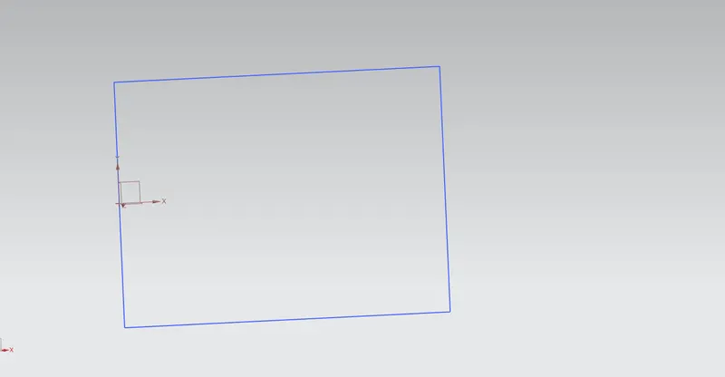
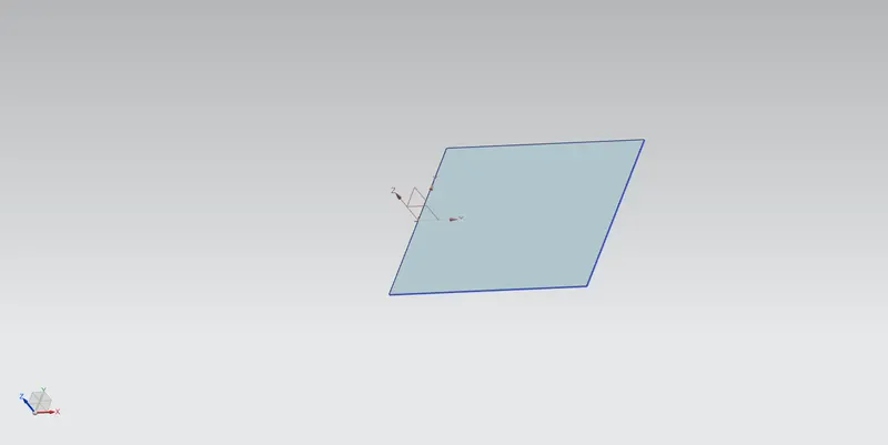
2. FLANGE -XY :
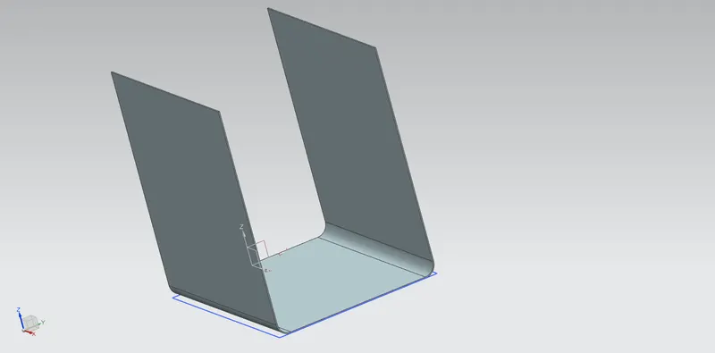
3. FLANGE - XZ :
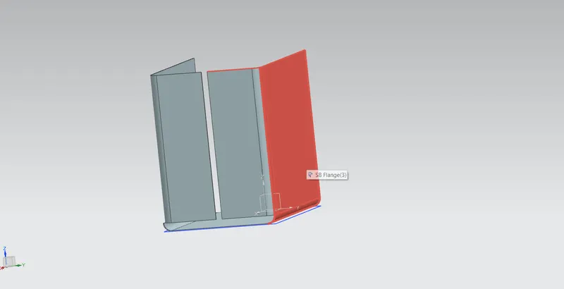
4. CLOSED CORNERS :
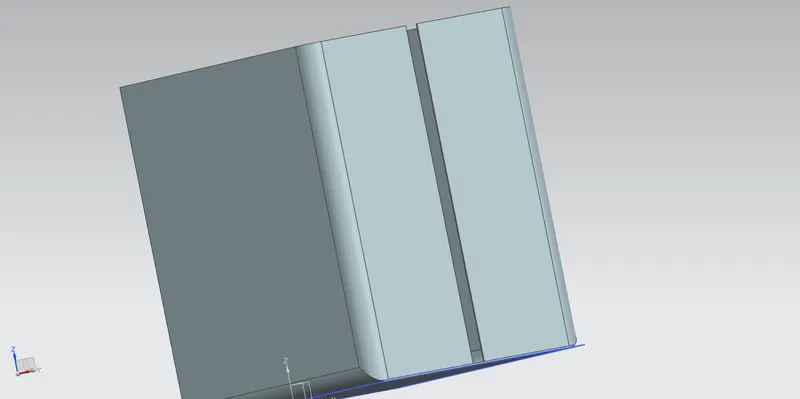
5. HEM :
- FLANGE -
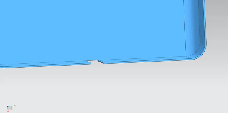
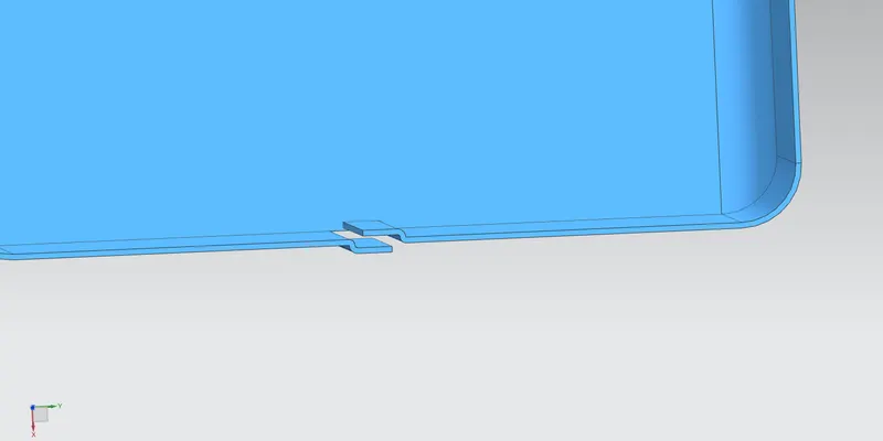
- HEM -
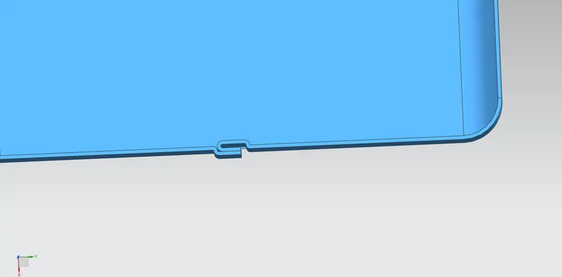
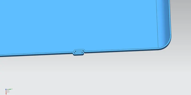
6. MIRROR BODY -
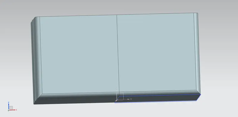
7. DIMPLE :
- DIMPLE SKETCH -
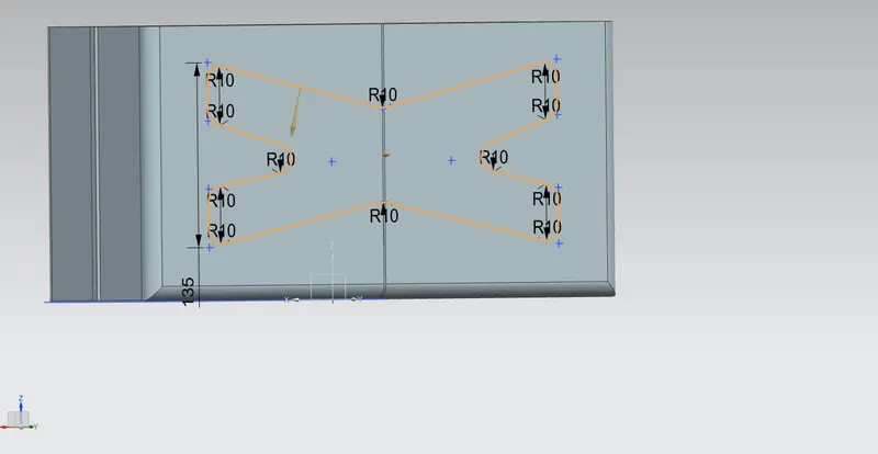
- DIMPLE :
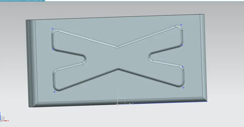
- MIRROR FEATURE DIMPLE -
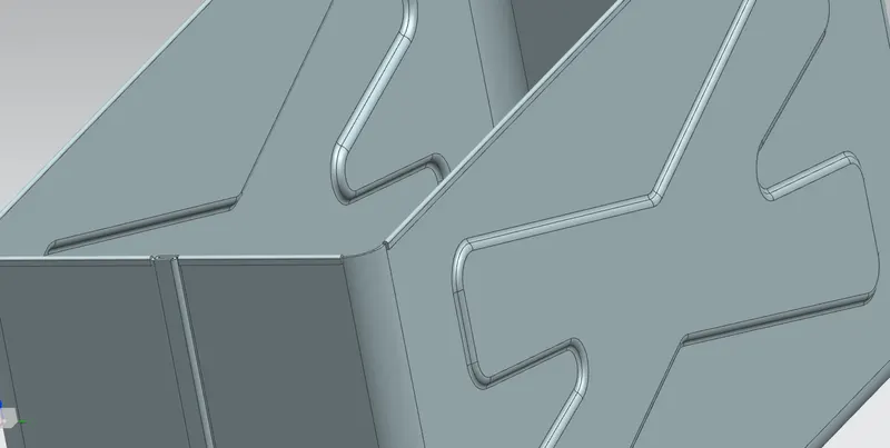
- DIMPLE SKETCH :
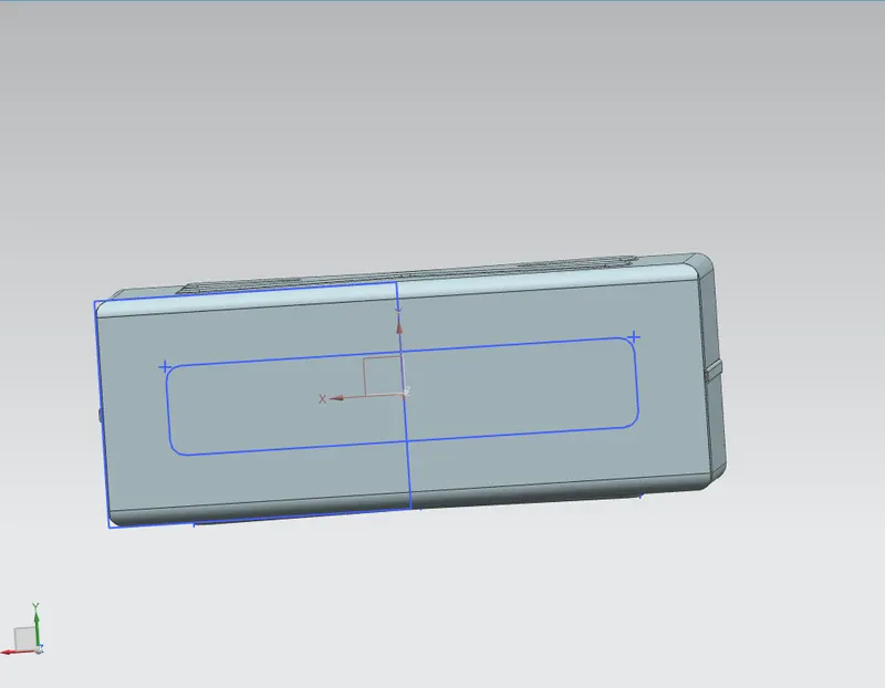
- DIMPLE -
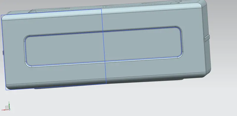
8. UNBEND & REBEND :
- UNBEND -
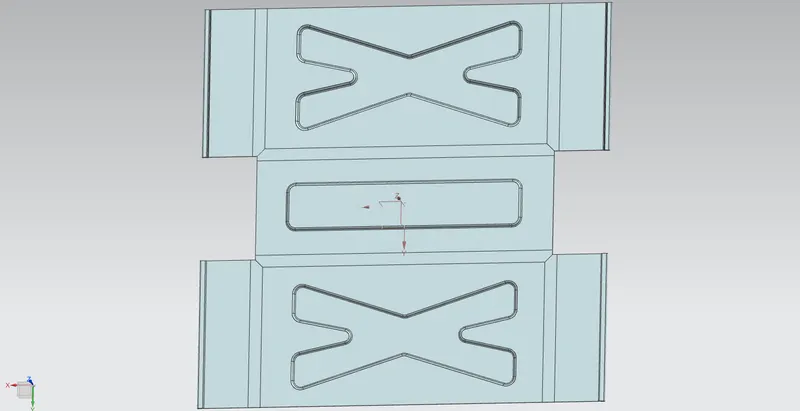
- REBEND -
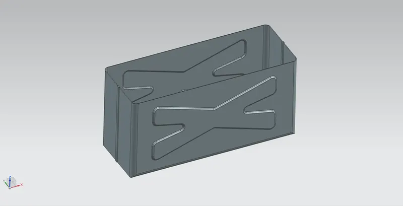
9. BEAD :
- BEAD SKETCH :
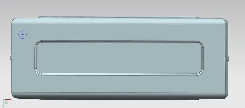
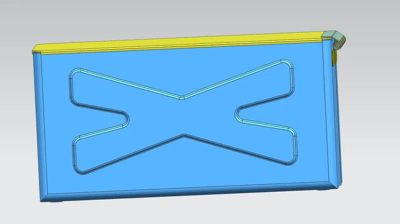
- BEAD -
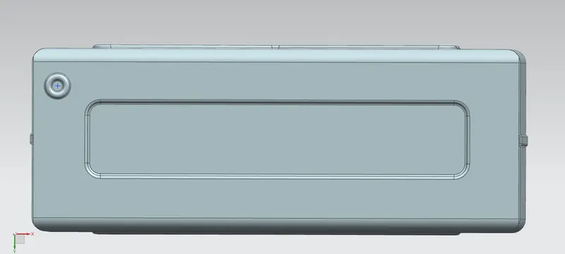
- BEAD BY MIRROR FEATURE :
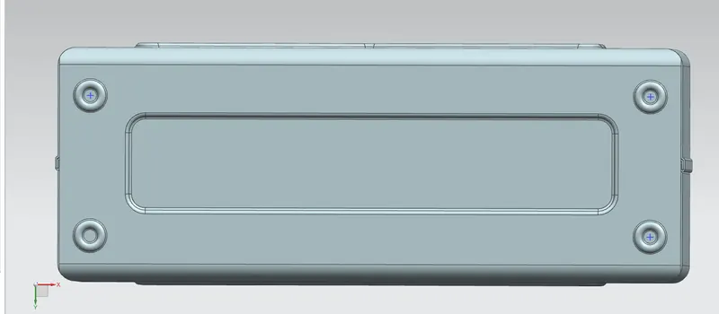
10. HEM :
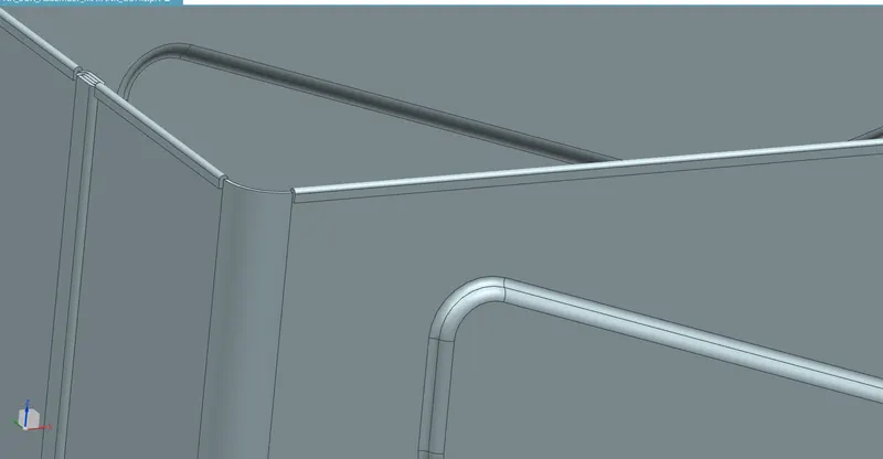
11. LID :
- LID DATUM PLANE -
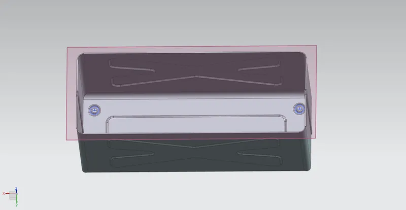
- LID SKETCH -
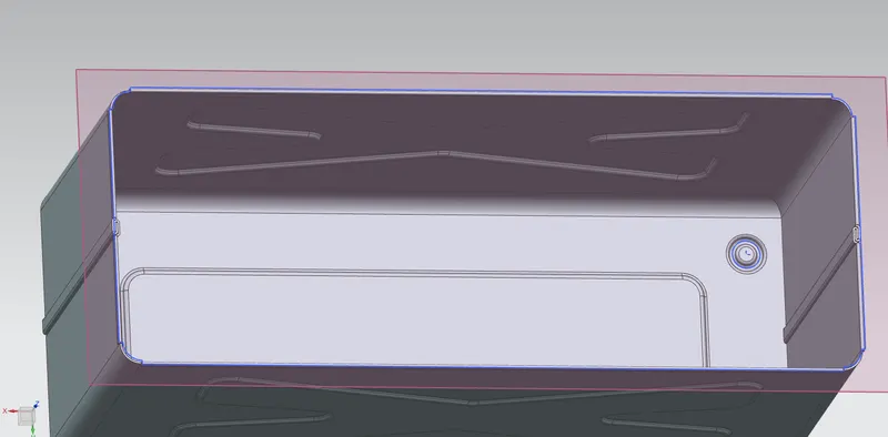
- LID -
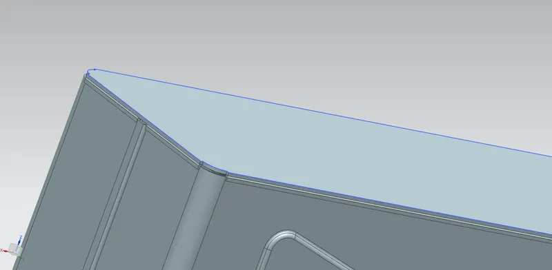
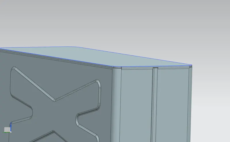
- LID FLANGE -
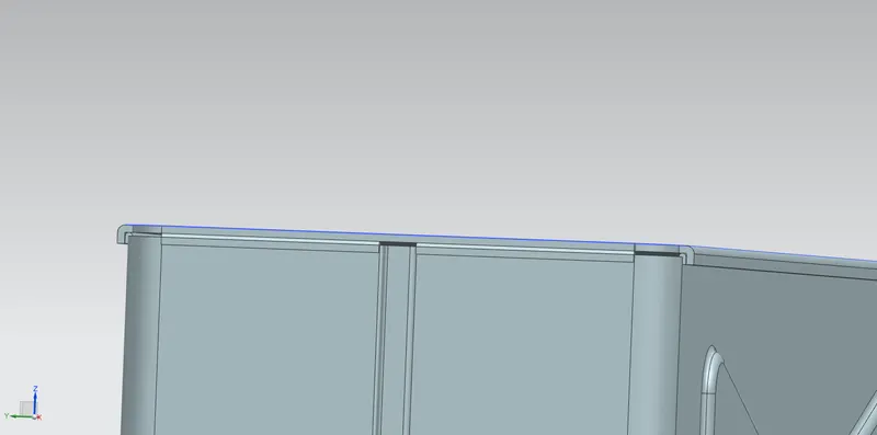
12. TAB :
- TAB SKETCH -
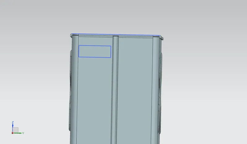
- TAB -
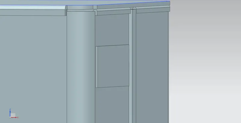
- TAB CORNER BREAK -
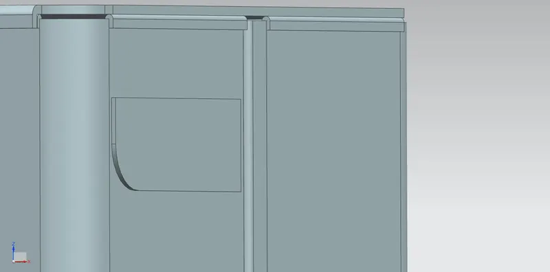
- FLANGE -
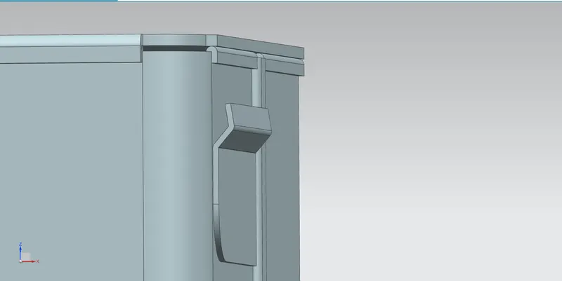
- HEM -
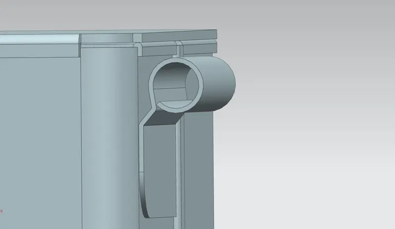
- UNBEND -
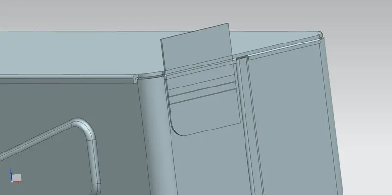
- SKETCH FOR NORMAL CUTOUT -
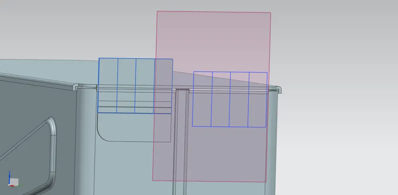
- NORMAL CUTOUT -
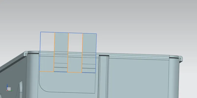
- REBEND -
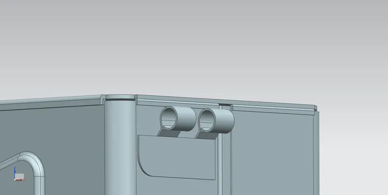
- MIRROR FEATURE -
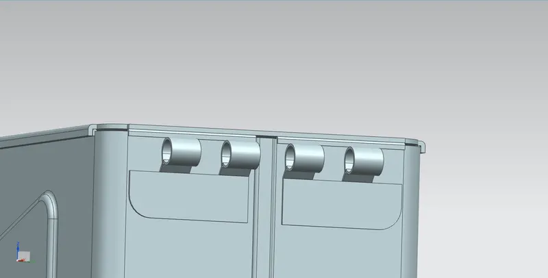
13. TAB AT UPPER LID -
- TAB -
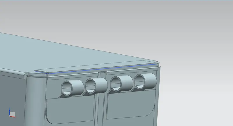
- TAB CORNER BREAK -
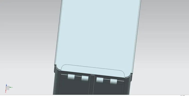
- FLANGE -
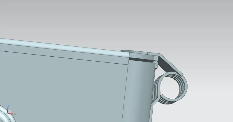
- UNBEND AFTER HEM OPERATION -
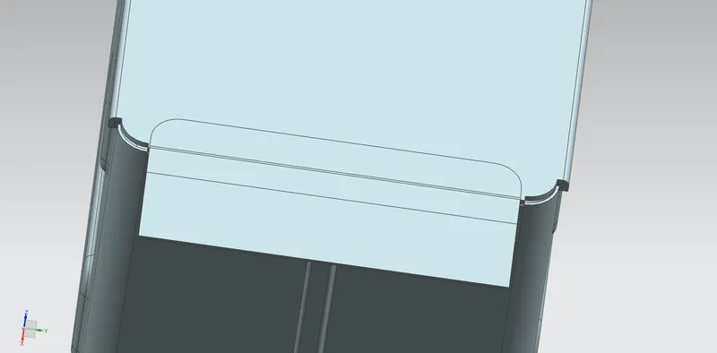
- SKETCH FOR NORMAL CUTOUT -
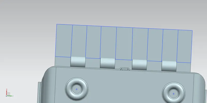
- NORMAL CUTOUT -
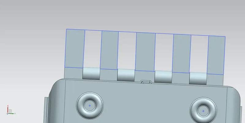
- REBEND -
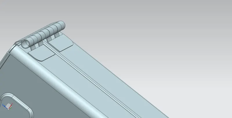
13. DRAFTING :
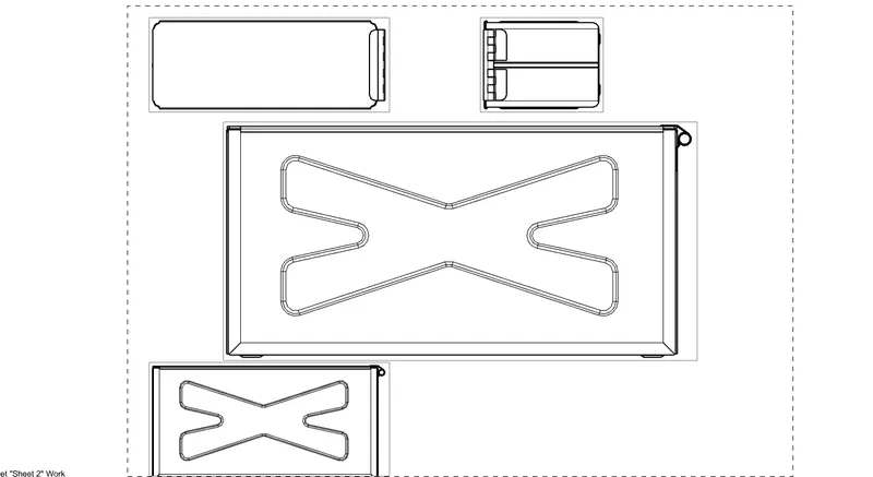
FINAL ASSEMBLY :-
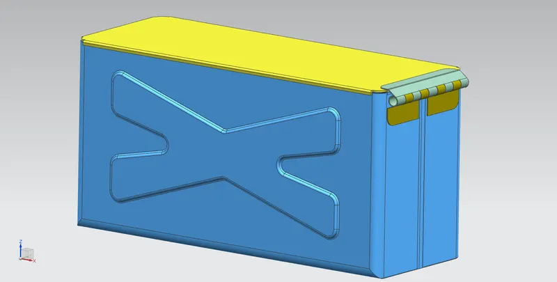
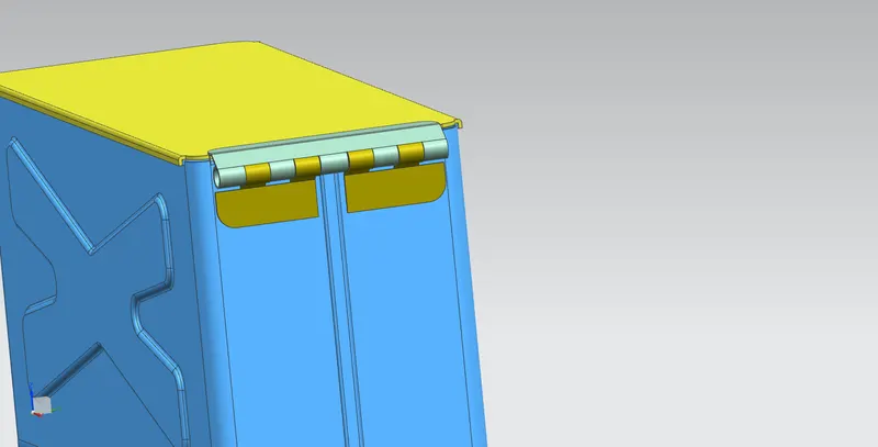
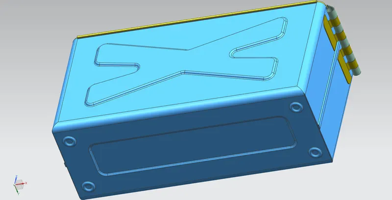
CONCLUSION :
- Learned all the functions or command of Advanced sheet metal designing - NX Cad.
- As per the given data have designed BOX ASSEMBLY & made flowchart to understand the flow of design process in future.
- Learned how to create detailed drawing using Drafting feature.