Fender Design Challenge
Aim:
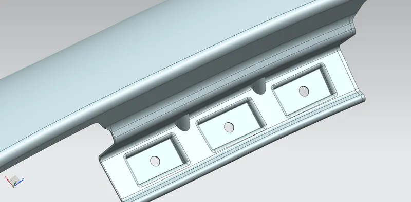
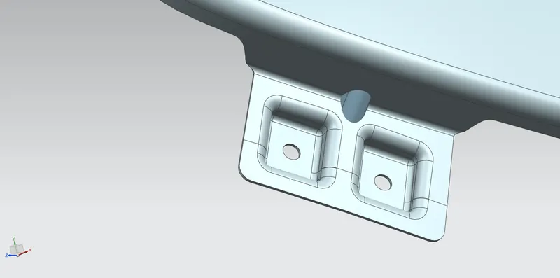
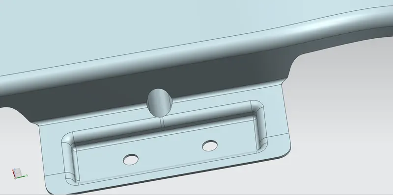
To design Front FENDER mounting areas Sill, Bumper, Baffle and A- pillar by using given design data.
Given Data:
- Styling surface of FENDER
- Drip area standard dimensions data.
DEFINITION OF FENDER:
- Fender is US English term for part of a automobile that frames a wheel well.
- Fender is situated above the wheel of the car to prevent from sand, rocks, liquid and road spray during rotation of tire. Also reduces pedestrian vehicle collision and prevent throwing up of debris to nearby vehicles.
- Most of the passenger vehicles have 4 fenders, 2 Front fenders – 2 Rear fenders. Usually the front fender is designed separately; the rear fender comes along with the body structure.
MANUFACTURING PROCESSES:
1. Embossoing:
- Embossing is a metal foaming pricess for producing raised or sunken desgns or relief in sheet material by means of matched male and female roller dies, theoretically with no change in metal thocknes, or by passing sheet or a strip of metal between rolls of the desired pattern.
- Metal sheet in drown through the male and female roller dies prodicing a apattern or design on the sheet. Depending on the roller dies used, different patterns can be produced on the metal sheet.
2. Cutting and Blanking:
- Cutting processes are those in which a piece of sheet metal is separeted by applying a great enough shearing force to cause the material to fail.
- Blanking is a steel manufacturing process in which a flat, geometric shape is created by feeding a acoil of sheet metal into a press and die. In this process, the blank is punched out from the large metal sheet.
Types of FENDER:
- FULL BUMPER TYPE FENDER: Conventional type used in this bumper. This fender covers the wheel almost eighty percent as shown in the pic.
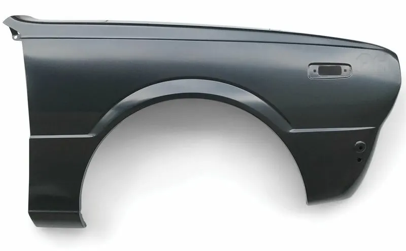
2.HALF BUMPER TYPE FENDER: As shown in the attached pic this type of bumper helps in reducing the weight of fender at the same time it improves the safety of pedestrian moving
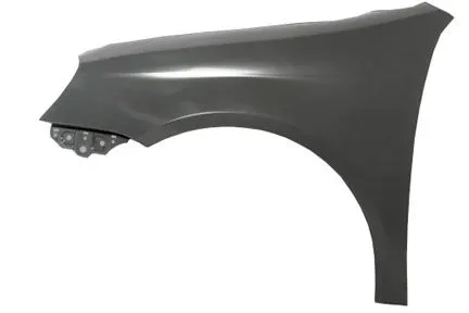
FENDER DESIGN:
- FENDER MOUNTING AREAS
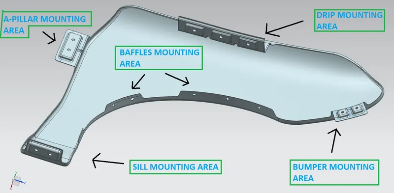
Designing Software : NX Cade
Designing functions to be used :
- Surface Law Extention : To extend the sheet as per requred Length and Angle.
- Project Curve : To project a curve on working surface from Sketch.
- Curve on surface : To create curve on surface.
- Emboss:
- Face and Edge Blend:
- Dart:
- Thicken:
1. DRIP AREA:
- DESIGN CONSEDERATION AS BELOW
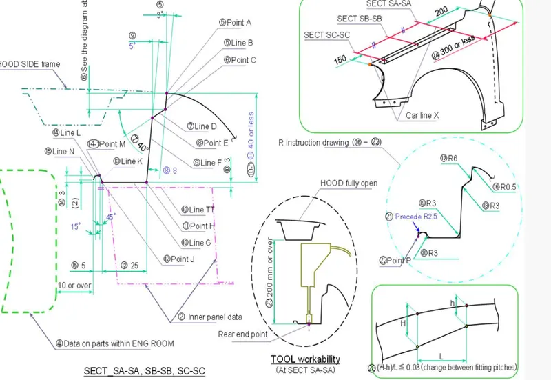
The area at which the fender gets attached to the engine housing through fastners. Design dimension used as per above attached standard data.
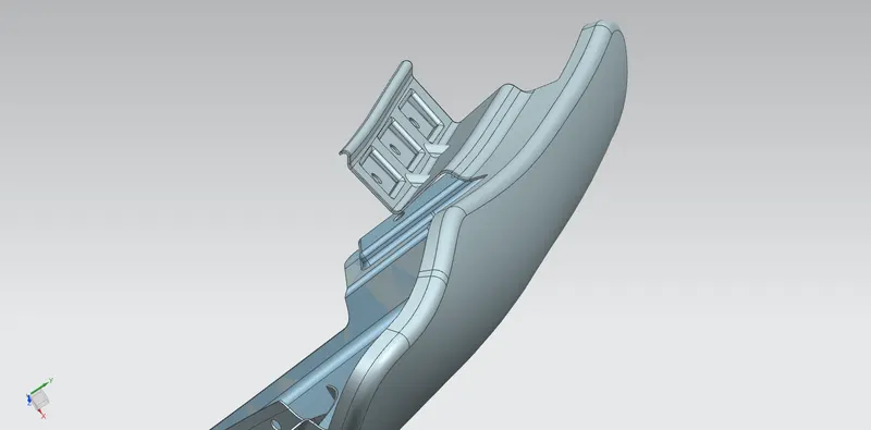
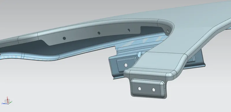
2.SILL MOUNTING AREA :
The area at the which the bottom of the fender gets connected to the floor near the bottom edge of the door. The Embossed sill mount will be assemble through fastners.
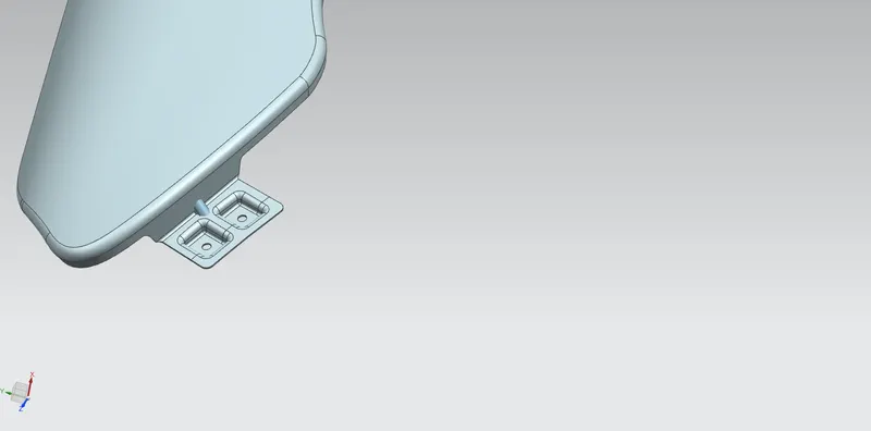
3. Bumper Mounting Area:
The bumper mounting region is located bebeath the bumper. The fender gets attached before the installation of the bumper.
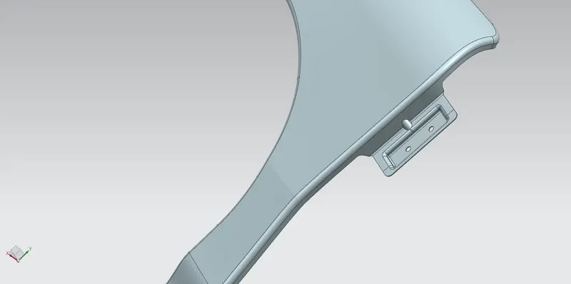
4. A- PILLAR MOUNTING AREA:
This mounting region is located near the cowl of the vehicle where the fender is fastened with bottom edge of the windshield. This mounting is covered with the side rear view mirror.
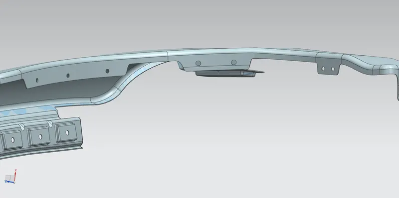
5. BAFFLE MOUNTING AREA:
In this specific region, the baffle gets installed to the fnder with the help of clips which holds the baffle with the fender along the arc wheel.
DART CREATION:
Darts are provided at the bends to stiffen the sheet metal at that region.