Advanced Sheet Metal Design Using NX Cad Challenge_2_Box Assembly
AIM : Advanced sheet metal design using NX cad challenge 2 Box Assembly .
OBJECTIVE : To design a BOX Assembly using Siemens NX sheet metal application.
INTRODUCTION :
SHEET METAL is metal formed by an industrial process into thin, flat pieces. Sheet metal is one of the fundamental forms used in metal working & it can be cut & and bent into a variety of shapes. Conties averyday objects are fabrication from sheet metal.
Applications : Aircraft bodies, automobile bodies, utensils used for domestic purpose, beverage cans.
the sheetmetal application provides an environment for the design of sheetmetal parts used in machinarey , automotive, aerospace etc.
By using sheetmetal Application We can do :
- Import, clean up, & a non-sheetmetal part to a valid sheetmetal part
- Export lat pattern data of sheetmetal part to a valid sheetmetal part.
Design Methodology :
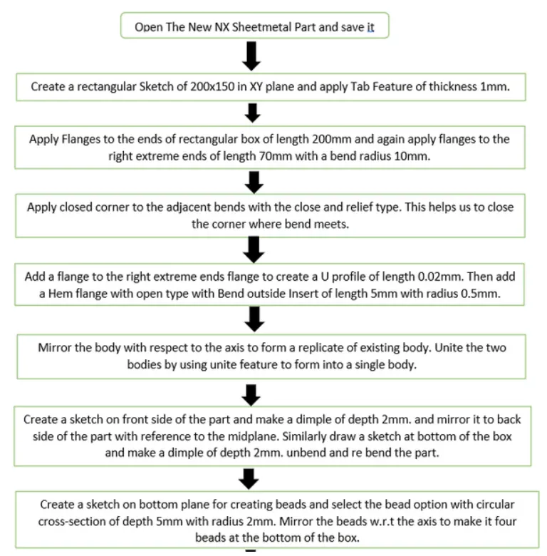
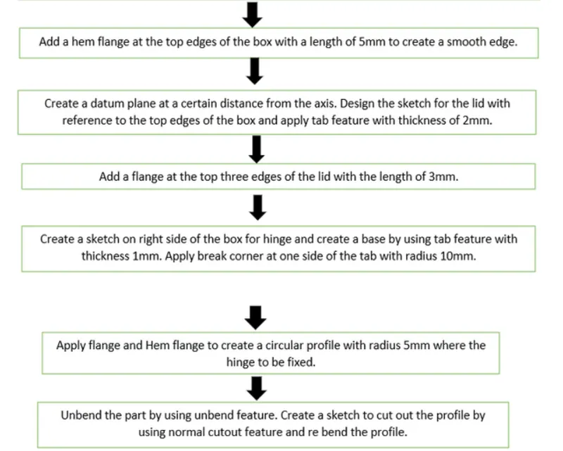
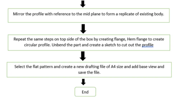
Description :
FEATURES USED :
SKETCH: It is basic command to draw to draw 2D models.
TAB : This command is used to create a base feature by extruding a sketch along vector by a thickness value or by adding material to exixting faces & bend regions of sheetmetal part.
FLANGE : This command is used to add a flat flange at a angle to the planar face & a bend between the two. A flange consists of bend region & a web.
CLOSED CORNER : This command is used to modify two flanges is one operation & to close the corner where the two flanges meet .
HEM FLANGE : This command is used to modify an edge of a sheetmetal part by folding it on to itself for the purpose safe handling or to increase edge stiffness.
MIRROR BODY : This command is used to mirror the part w.r.t the required axis.
UNITE : This command is used to combine the two parts into one part .
DIMPLE : This command is used to lift an area of the model inside the sketch that stimulates a stamping tool.
MIRROR FEATURE : This command is used to mirror the required sketch to other side with reference to the axis.
UNBEND : This command is used to flatten the 3D model by selecting one stationary face.
REBEND : This command is used to rebend the flatern sheet material.
BEAD : This command is used to lift material along contour of a sketch that stimulates a stamping tool. Bead can also be created to stiffen sheet material.
Image of BOX Assembly :
Front View :
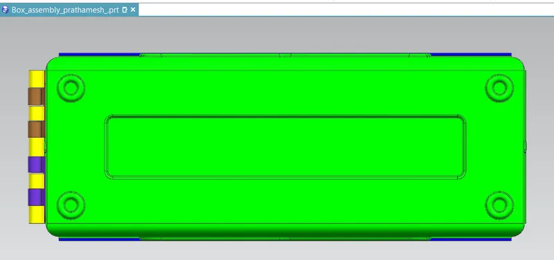
Back View :
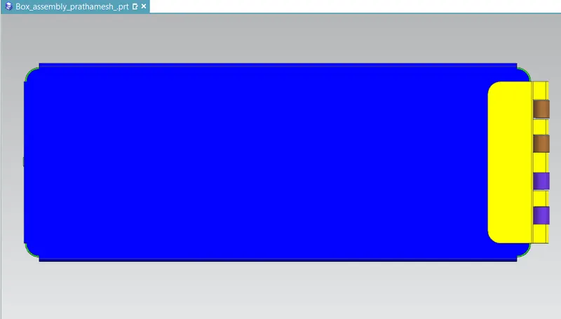
Top View :
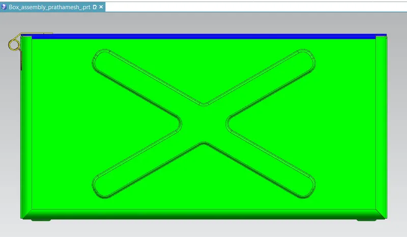
Front View :
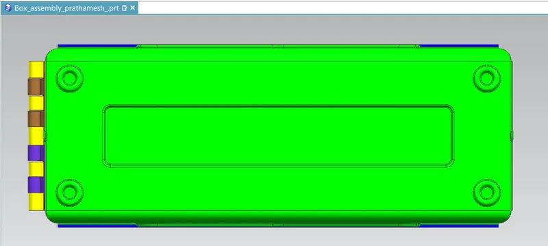
Bottom View :
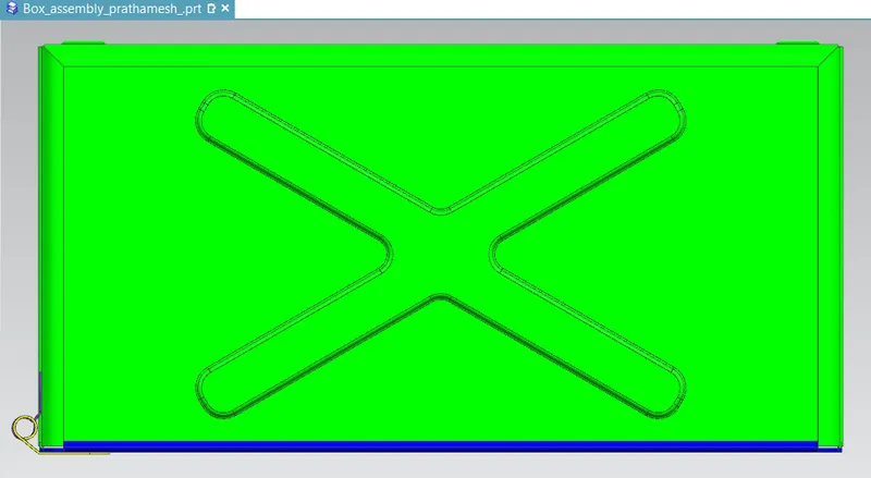
Right Side View :
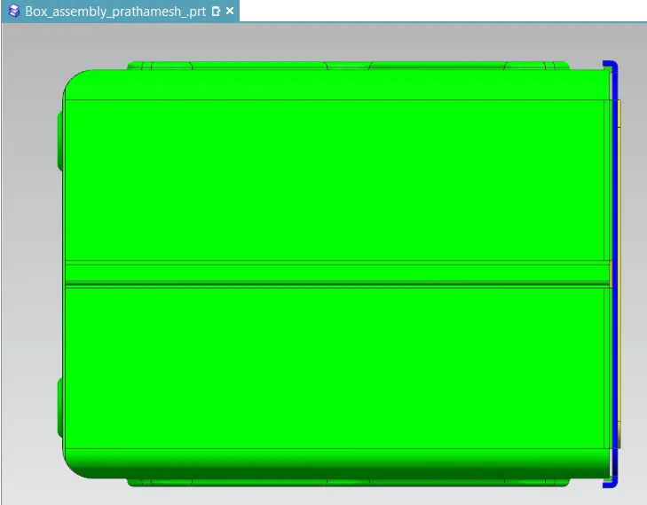
Left Side View :
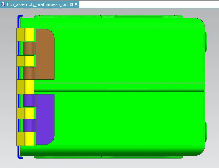
Isometric View :
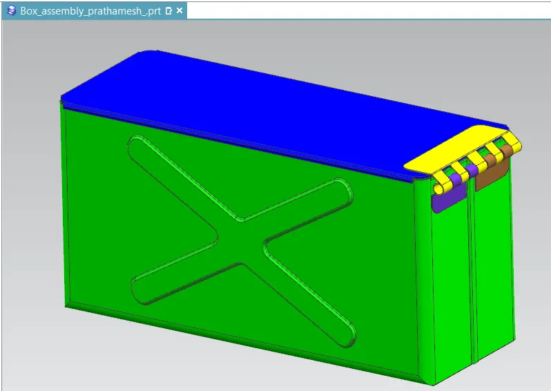
DRAFT DRAWING :
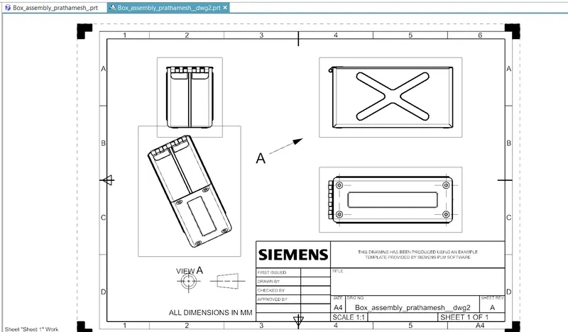
CONCLUSION :
By performing this task , I have learned how to use features like tab , break corner , closed corner , dimple, hem flange, bead, rebend , datum plane, datum plane coordinate system , flat pattern, mirror feature, mirror body , unite, normal cutout & unbend by creating a box assembly.