Week 2:- BiW Fixture Basics Challenge
Q.1) Project Execution Activity
Project Activity it starts with basic rquairment
1) RFQ Received
RFQ is basic request of coatation to the customer , where customer give the required specification ,documents etc. and form of to some of documents or data.
2) 1st Specification Discussion Meeting
To submit the document and accept the document ,check the dimensions and deadline.
3) Offer Submission
To check the customer requirements and accept it.
4) LOI/PO receipt
Recieved the LOI/PO then start the work , Then prepare the PO deviding the different activities in the project like process design, design data study ,3D design prparation ,Simulation , final DAP, BOP release,BOP indent,etc.
5) Shedule Preparation
Once Submit the design the start the preparation.
6) BOM preparation
BOM preparation is car box,required,cylinder are required check the requiredment and preparaed it.
7) Design Concept Preparation
Design the concept based on the all the specification ,all the data, PO/LOI recived the customer.3D data or 2D data of car panel or drawing standard.
8) Customer Approval
This process are complet the design concept process then go to the customer approval (DOB process) design approval process. to check design specification to provide him it considered or not all are ok then approval it and passed the next process.
9) Detailing And dwg. Release
This process to change the drawing like customer requirement add some clamps or dimensions changes etc.
10) Manufacturing BOP ordering
Start the manufacturing like risers,milers,clamps some other components and BOP ordering to get the sensors, cylinder as per the specification and other items.
11) Quality Inspection
Check each part of the drawing assembled because some errors like mechanical error Human error ,dimenstion error it check to the final assembly is important
12) Mechanical and Electrical assembley
Again to check the assembley to final product design all the dimenssion are check properly or CMM machin check.
13) Internal Trial and Testing
Is to check the product like drilling holes,to holding the BIW fixture to check the pin fixed in the fixture , clamping.
14) Online Trial
Online trial is to show the customer and approval it. and passed through the further process.
15) Packaging
Packaging the fixture because is important to transportation
16) Dispatch
Fixture is dispatch as per the installation Process.
17) Installation as per layout
Installation process is to mounted on robot,sensors etc. as per layout
18) Trials and Trainning at Customer
Installation process is complete then go to the trials. This process to guide or tranning for the operator
19) Buy Of Meeting
In this meeting to described the LOI or some modification of the product.
20) Final Handover
And final all are done the process.
Q.2) Types Of Joining Process
The durability and performance of any structure is largerly dependes on the qulity and the design of the component joints .
Two fundamental option for joining materials and components.
1. Mechanical Joining
2.Metallurgical Joining
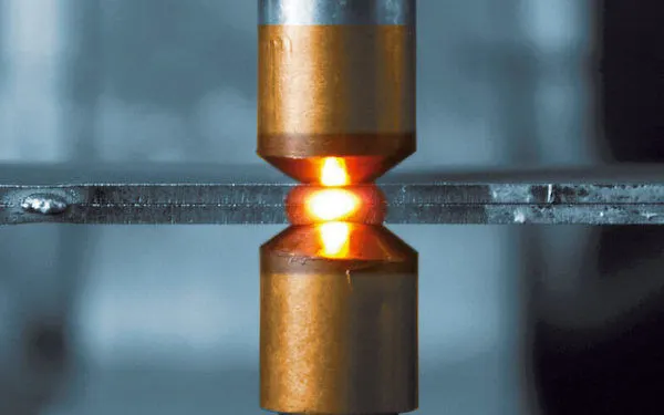
1.) Resistance Welding
Resistance Welding is a welding technology widely used in manufacturing industry for joining metal sheets and components.
2.) Resistance Projection Welding
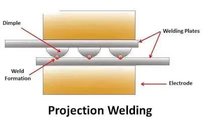
Projection Welding is a resistance welding process for joining metal components or sheet with embossments by directly applying opposing forces with electrods specially designed of fit the shapes of the workpiece.
3.) Resistance Spot Welding
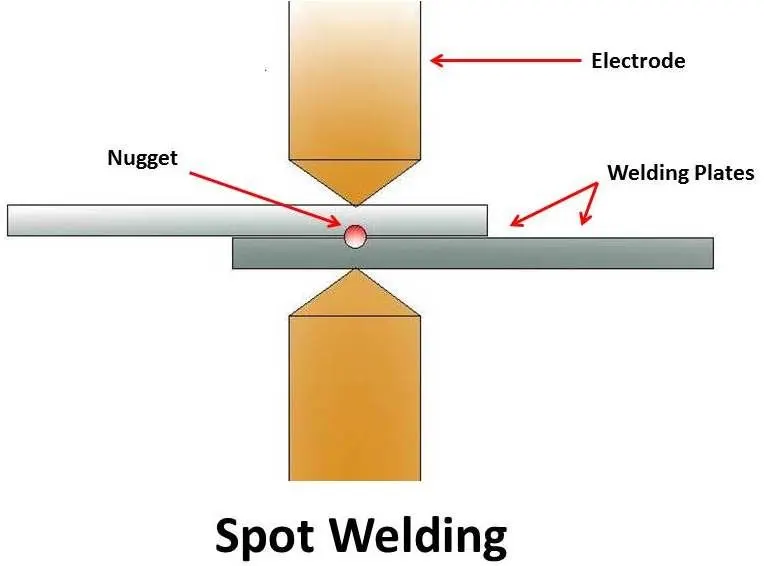
The process is used for joining sheet materials and uses shaped copper-chromium or zirconium alloy electrods do apply pressure and convey the electrical current through the workpieces.
4.) Resistance Seam Welding
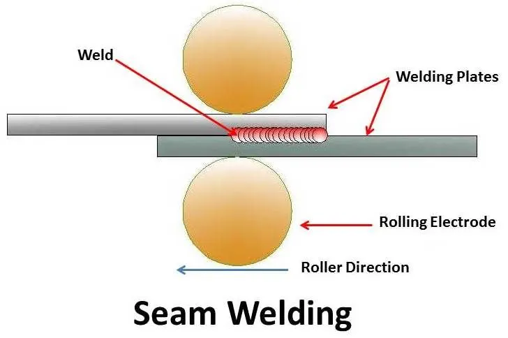
Seam Welding is a resistance welding process for joining metal sheets in continous ,often leack tight, seam joints by directly applying opposing forces with electrodes consisting of rotary wheels.
5.) Arc Welding
The process involved either consumable electrode (Rod or wire)
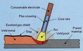
6.) Manual metal arc welding
Manual metal arc welding (MMA or MMAW) also known as shielded metal arc welding (SMAV),or informally as stick welding
Stick welding is a struck between the metal rod and the work piece,both the rod and work piece surface melt to creat a weld.
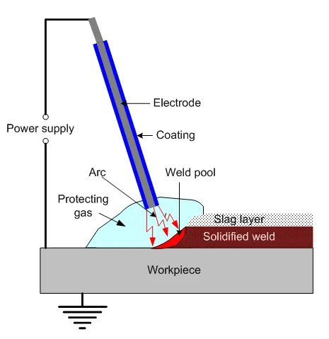
7.) Gas-shielded metal arc welding (Metal inert gas (MIG)welding)
Metal ienrt gas (MIG) welding in an arc welding technique in which a consumable electrode is used to weld two or more work pieces.
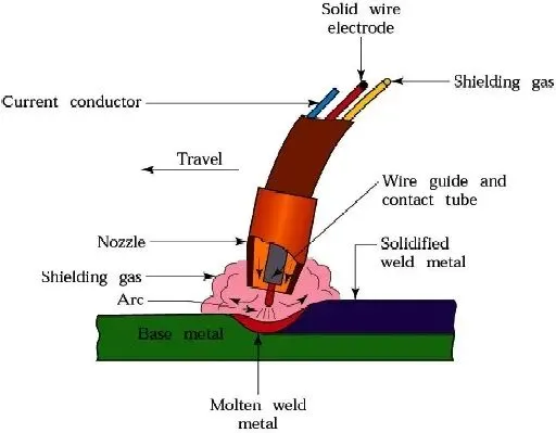
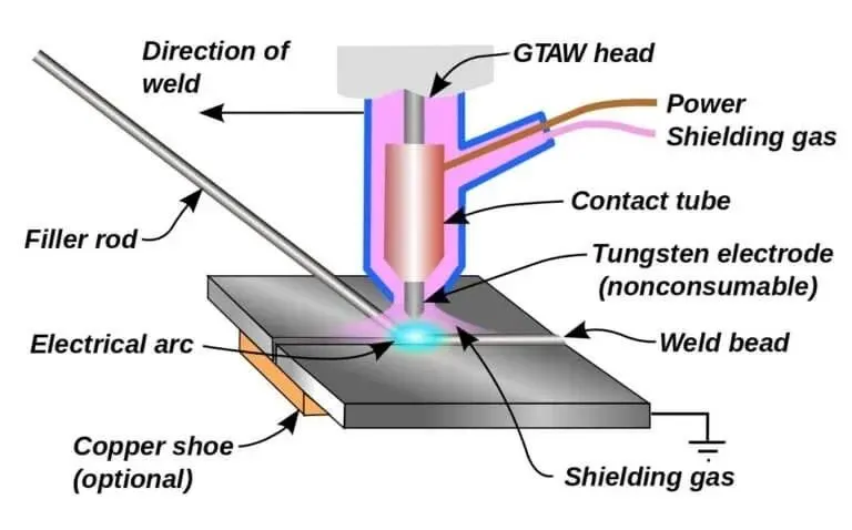
8.) GAS-Shielded tungsten arc welding (Tungsten inert gas(TIG)welding)
Is an arc welding method that uses a non consumable tungsten electrode to weld two or more workpieces. It is very much similar to metal arc inert gas welding.
9.) Mechanical Fastening
The Joining Of materials combinations which cannot be easily welded such as pre-painted steels or very dissimilar metals.
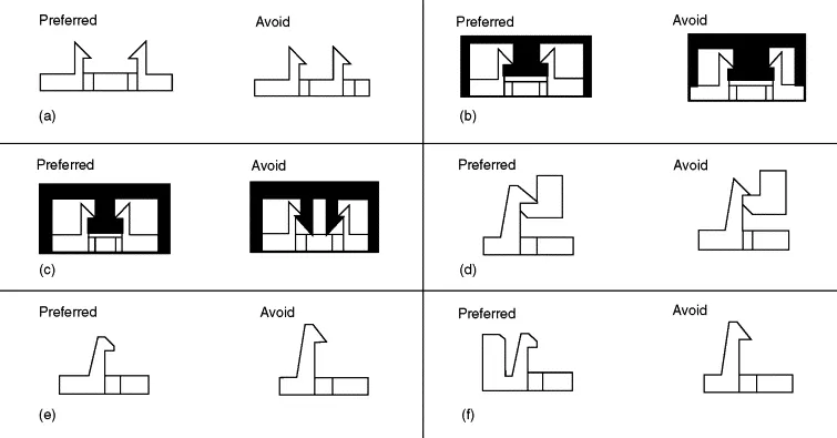
10) Self Piercing riveting.
Self piercing riviting is a high speed mechanical fastening process for point joining sheet material,typically steels and aluminium alloys.
It is a single step technique,generally using a semi-tubular rivet to which the sheets in a mechanical joint.
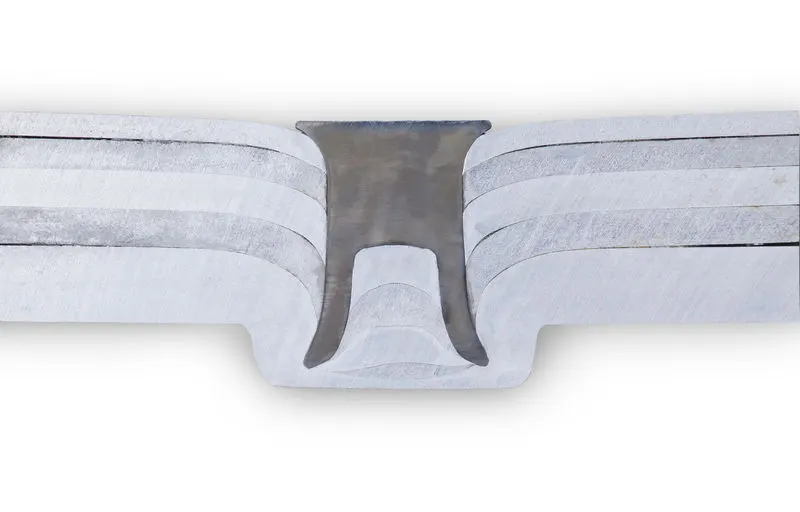
11) Hemming Process
Hemming is the process in which the edge is rolled to itself ,which a seem joins the edges of two materials
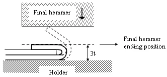
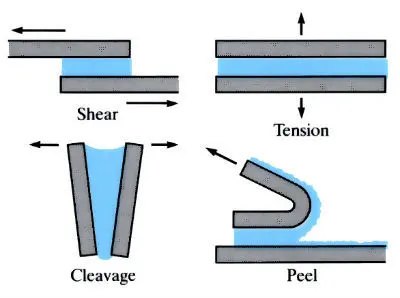
12.) Adhesive Bonding
Adhesive Bonding is used to fasten two surface together,usually producing a smooth bond.
Q.3) Resistance Welding :
Resistance welding is the joining of metals by applying pressure and passing current for a length of time through the metal area which is to be joined. The key advantage of resistance welding is that no other materials are needed to create the bond, which makes this process extremely cost effective.
There are several different forms of resistance welding (e.g. spot and seam, projection, flash, and upset welding) which differ primarily by the types and shapes of weld electrodes that are used to apply the pressure and conduct the current. The electrodes, typically manufactured from copper based alloys due to superior conductive properties, are cooled by water flowing through cavities inside the electrode and the other conductive tooling of the resistance welding machine.
Resistance welding machines are designed and built for a wide range of automotive, aerospace and industrial applications. Through automation, the action of these machines is highly controlled and repeatable allowing manufacturers to staff production readily.
The resistance welding working principle is that the application of current and force through the welded parts develops resistance and thus creates a nugget in the melt joint. Even when there is the passage of a large amount of current, no electric shock is caused as minimal voltages are applied.
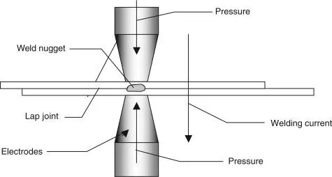
Application In Automotive Sector:
Resistance Spot Welding (often just called spot welding) is a cost-effective joining technology that continues to be very popular in the automotive industry where high reproducibility and automation are essential criteria. ... Resistance Spot Welding is a pressure welding process.
It is used in welding bars, boxes, cans, rods, pipes and frames metals of medium and high resistance materials such as steel, stainless steel, monei metal and silicon bronze which are easy to weld. It is used for making cutting tools.
Q.4) Fusion Welding.
Fusion welding processes can be grouped according to the source of the heat, for example, electric arc, gas, electrical resistance and high energy.
In addition to arc and laser welding, there's the fusion welding process known as induction welding. ... With induction welding, a wrapped coil is used to create a magnetic field that heats metal. The magnetic field quickly heats the metal, causing to melt and fuse together.
5 Types of Fusion Welding
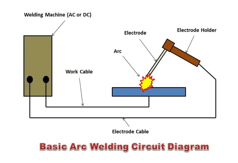
1.) Arc Welding.
The most popular type of fusion welding is arc welding. Arc welding lives up to its namesake by relying on an electric arc to join two or more objects. With electric arcs measuring up to 6,000 degrees Fahrenheit, this fusion welding process is highly capable of melting even toughest metals. Furthermore, arc welding can be performed underwater, making it an ideal solution for offshore welding projects.
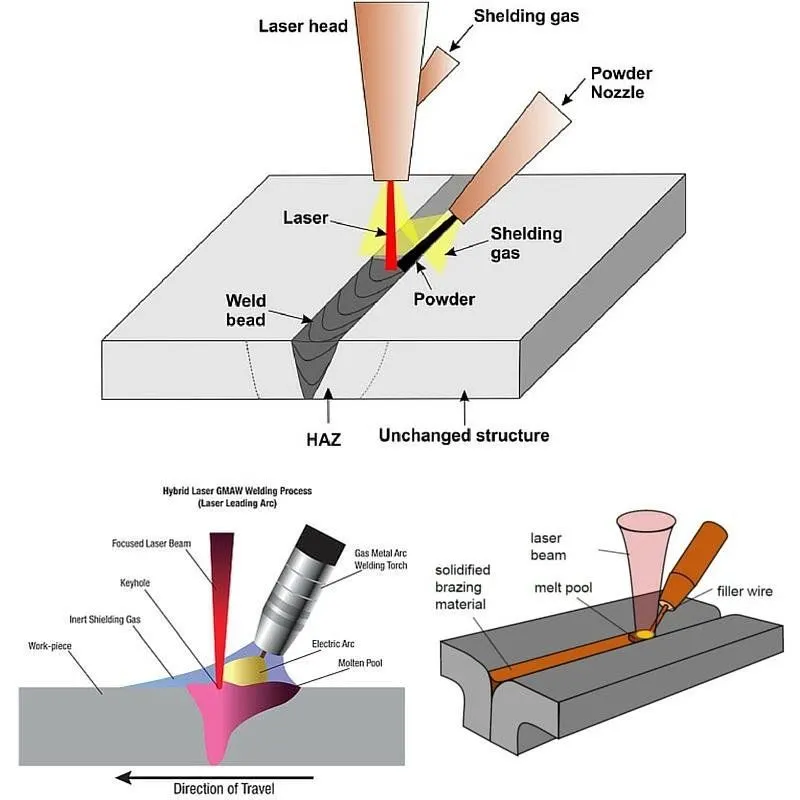
2.) Laser Welding.
Another type of fusion welding is laser welding. Also known as laser welding, it involves the use of light radiation to produce heat. The laser welding rig essentially blasts the surfaces with radiated light. With each blast, the surfaces become a little hotter. As the objects melt, they fuse together.
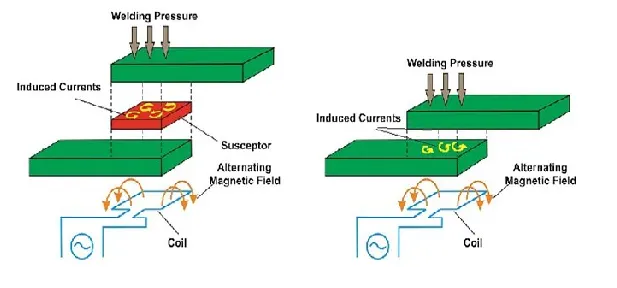
3.) Induction Welding.
In addition to arc and laser welding, there’s the fusion welding process known as induction welding. Induction welding is distinguished from all other types of fusion welding because it’s the only one in which there’s no direct contact between an object’s surface and the heat source. With induction welding, a wrapped coil is used to create a magnetic field that heats metal. The magnetic field quickly heats the metal, causing to melt and fuse together.
4.) Oxyfuel Welding.
A type of chemical-based fusion welding, oxyfuel welding involves the use of a flame to heat and join surfaces, with oxygen as the fuel source. Fire, of course, needs oxygen, which is the basis on which oxyfuel welding works. The oxygen fuels the fire to create a hot flame in excess of 4,500 degrees Fahrenheit. Oxyfuel welding typically uses a combination of oxygen and a flammable gas to create a hot flame to join objects.
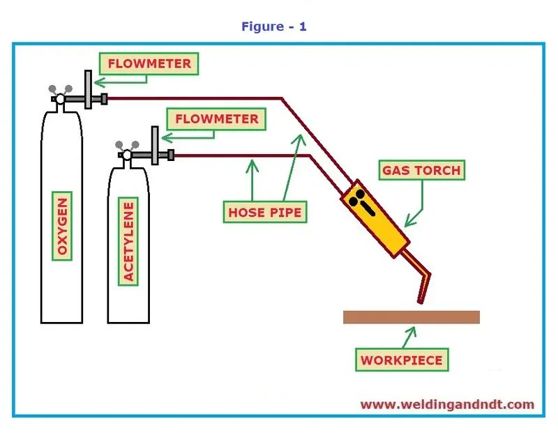
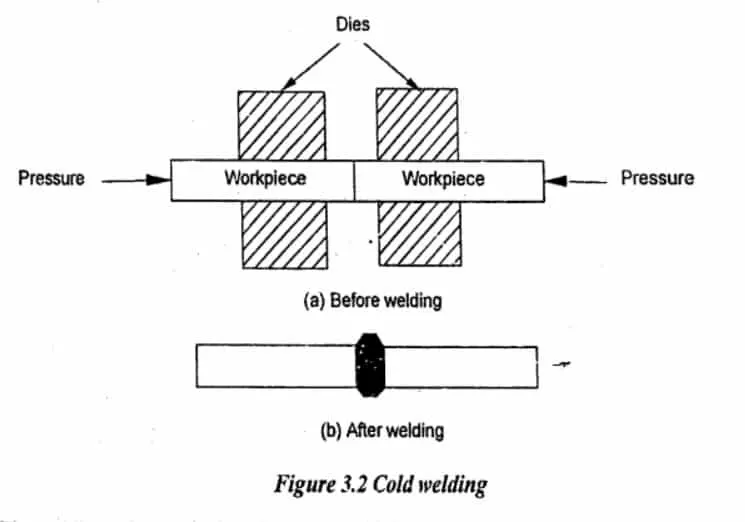
5.) Solid Reactant Welding.
Finally, solid reactant welding is a type of fusion welding that relies on chemical reactions with certain materials to join them. There are compounds, for instance, that create heat when mixed together. Solid reactant welding uses this principle to join two or more objects.
Application in the automotive sector:
Fusion welding processes are commonly used across a range of industries including aerospace, automotive and construction amongst others. Used to join metals for a variety of applications, fusion welding is also used to create artwork by a growing community of artists.
Q.5) 3-2-1 principle
A fundamental concern in metalworking is locating the part to be machined, punched, bent, or stamped relative to the work platform (fixture). For example, a CNC machine tool starts its process at a specific point relative to the fixture and proceeds from there. Hence, the accuracy with which a part is machined is quite dependent on the accuracy with which it is positioned in the fixture.
Accurate locating of not just one part, but each and every part that is loaded into the fixture is crucial. Any variation in part location on the fixture adds to the dimensional tolerance that must be assigned to the finished parts.
Additionally, the method of supporting and securing the part in the fixture affects not only dimensional tolerances, but surface finishes as well. This is true because improper supporting or clamping can temporarily or permanently deform the part. Hence, techniques for supporting and clamping must be considered together with the method of locating in order to assure repeatability from part-to-part.
Locating of a part to be machined is a three-step process:
1. Supporting
2. Locating (positioning)
3. Holding (clamping)
The Locating Process: Degrees of Freedom:
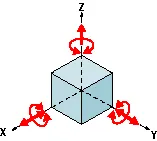
In order to completely specify the position in space of a three-dimensional
object (such as the cube that’s shown), we refer to six coordinates:
- Translational position along the X-axis
- Translational position along the Y-axis
- Translational position along the Z-axis
- Rotational position about the X-axis
- Rotational position about the Y-axis
- Rotational position about the Z-axis.
These six coordinates are known as the six degrees of freedom of a three-dimensional object. As the double-headed arrows indicate, the translational and rotational positions can vary in either direction with respect to each of the three axes.
To completely prevent movement, all six degrees of freedom must be restricted.
Locating Process 3-2-1 Method.
We have two objectives when mounting a part in a fixture for machining:
1. Accurately position the part at the desired coordinates.
2. Restrict all six degrees of freedom so that the part cannot move.
A widely used method of accomplishing these two objectives uses the 3-2-1 principle, so-called because it entails three steps that employ three, then two, then one fixed points of known location. Since that adds up to six fixed points, it’s also known as the six point method.
In the three steps of the 3-2-1 method, three mutually perpendicular planes, called datum planes, are introduced, one at each step. These three planes define the workpiece position, and together with opposing clamping forces fully constrain the part. Let’s take a look at the details of the 3-2-1 method.
Q.6) Body coordinate system:
Coordinate systems allow you to keep track of an aircraft or spacecraft position and orientation in space. The Aerospace Blockset coordinate systems are based on these underlying concepts from geodesy, astronomy, and physics.
An inertial frame is a nonaccelerating motion reference frame. In an inertial frame, Newton's second law holds: force = mass x acceleration. Loosely speaking, acceleration is defined with respect to the distant cosmos, and an inertial frame is often said to be nonaccelerated with respect to the fixed stars. Because the Earth and stars move so slowly with respect to one another, this assumption is a very accurate approximation.
A constant rotation about an axis written in the Body system is made up of the three rotations. The origin of the body coordinate system will be at the center of mass. ... The axes of the body coordinate system will be the principal axes of the object. These axes are rotating with the object.
The noninertial body coordinate system is fixed in both origin and orientation to the moving craft. The craft is assumed to be rigid.
The orientation of the body coordinate axes is fixed in the shape of body.
-
The x-axis points through the nose of the craft.
-
The y-axis points to the right of the x-axis (facing in the pilot's direction of view), perpendicular to the x-axis.
-
The z-axis points down through the bottom the craft, perpendicular to the xy plane and satisfying the RH rule.
Q.7) Elaborate Body plane system :
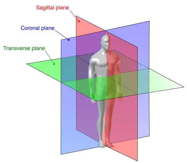
Body planes are hypothetical geometric planes used to divide the body into sections. They are commonly used in both human and zoological anatomy to describe the location or direction of bodily structures. Reference planes are the standard planes used in anatomical terminology and include:
- The sagittal plane (lateral or Y-Z plane) divides the body into sinister and dexter (left and right) sides. The midsagittal (median) plane is in the midline through the center of the body, and all other sagittal planes are parallel to it.
- The coronal plane (frontal or Y-X plane) divides the body into dorsal and ventral (back and front) portions. It also separates the anterior and posterior portions.
- The transverse plane (axial or X-Z plane) divides the body into superior and inferior (head and tail) portions. It is typically a horizontal plane through the center of the body and is parallel to the ground.
While these are the major reference planes of the body, other planes are commonly used in relation to these three. A longitudinal plane is any plane perpendicular to the transverse plane, while parasaggital planes are parallel to the saggital plane.
The coronal plane, the sagittal plane, and the parasaggital planes are examples of longitudinal
planes.
Anatomical Planes in a Human:
There are three basic planes in zoological anatomy: sagittal, coronal, and transverse. A human in the anatomical position, can be described using a coordinate system with the Z-axis going from front to back, the X-axis going from left to right, and the Y-axis going from up to down.
Applications of Body Plane :
Medical imaging techniques such as sonography, CT scans, MRI scans, or PET scans are one of the primary applications of body planes. By imaging a patient in standard anatomical position, a radiologist can build an X-Y-Z axis around the patient to apply body planes to the images. The planes can then be used to identify and locate the positions of the patient’s internal organs. Individual organs can also be divided by planes to help identify smaller structures within that organ.
Body planes are used to describe anatomical motion in the X-Y-Z coordinate system that the body moves through. An anatomist could model a limb’s range of motion by measuring which planes the limb can move through and how far it is able to travel.
Anatomical change during embryological development is also described and measured with body planes. For example, during human embryonic development the coronal plane is horizontal, but becomes vertical as the embryo develops into a fetus. In comparative embryology, body planes provide a basis for comparing the ways in which different types of organisms develop anatomically within the womb.