Week 1:- Introduction to BiW and Fixtures Challenge
Q1). BIW(Body In White)
Body In White is define to refers to the welded sheet metal components which from the vehicles structures to which the other components will be married i.e. engines, chasis,exterior and interior trim.
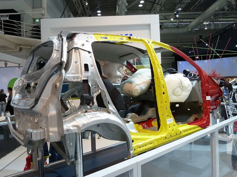
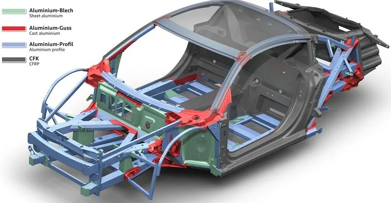
BIW Parts:-
1) Body Sides :-
1. Body side outer.
2. Body side inner.
2) Under Body :-
1. Front end under frame.
2. Main Floor.
3. Rear end under frame.
3) Closures :-
1. Front door.
2. Rear door.
3. Hood.
4. Decklid.
4) Roof :-
1. Roof inner.
2. Roof Outer.
5) Fender
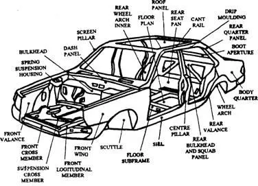
Q2). BIW Nomenclature :-
Nomenclature is basically choosing a names for things. BIW have number of parts in it. All parts have different names. i.e. Suspention tower , Inner wing Panel, Upeer Wing member, Roof Stifener etc.
Q3). FIXTURE
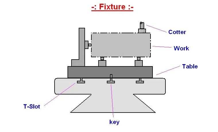
A Fixture device designed and build for holding a particular piece of work for machining operations. Fixture is hold and position the work but dose not guide the tool. by using 3-2-1 principle
Types Of Fixture :-
1). Production Fixture
In this fixture generally used in mass production purpose .
2). Pre production Operation fixture(PPO)
For initial batch production to study the feasibility.
3). Checking Fixture
For car panel geometric inspection purpose.
Q.4). Basic Principle Of Fixture Design :-
For a fixture designer , the major portion of design time is spent deciding how to locate the work piece in the fixture.
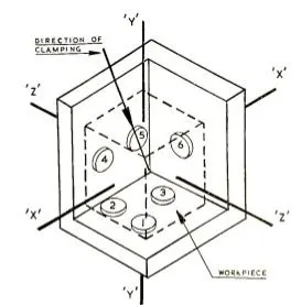
For any free body there are total of twelve degrees of freedom as below
6 translational degrees of freedom: +X,-X,+Y,-Y,+Z,-
And 6 rotational degrees of freedom :
- Clockwise around X axis (CROT-X)
- Anticlockwise around Y axis (ACROT-X)
- Clockwise around Y axis (CROT-Y)
- Anticlockwise around Y axis (ACROT-Y)
- Clockwise around Z axis (CROT-Z)
- Anticlockwise around Z axis (ACROT-Z)
The 3-2-1 method is a work-holding principle where three pins are located on the 1st principle plane, i.e., either XY, YZ, ZX. And two pins are located on the 2nd plane perpendicular to the 1st plane, and at last, one pin on the plane is mutually perpendicular to the 1st and 2nd planes. The aim is to constrain the movement of the workpiece along all three axes.
Q.5). Types of BIW Stations:
1. Geo Tool
In this station geometry of two parts are fixed. it can be either using welding or riveting. In this station precision and geomatry of the finished product is defined locating pins have closer tolerence of 0/-0.15.
2. Respot Tool
Once product comes out of the geo station and there are left out spots where spot welding or riveting is to be done. then it is moved to another station, that station is called respot station.
In this station pins have tolerance of 0/-0.28.
3.Marriage or Hemming Tool
A marrige or a hemming tool is a fixture in which the inner panel assembly and outer panel assembly are joined together.
These are done by welding or by hemming in case of closure panels.
4. Loading Station
This station is used for loading of panel and same station is used to change the orientation of the if it is required in the upcomin station.
5. Buffer Station
This station is used to make the balance between the process.Some stations carry out procees in lesser time as compared to their respective stations.In that case panels can be stored in one sation so that assembly line process remains smooth.
6. Sealer Station
In this station Sealant application is carried out.This process can be carried out manually or by using robots. Sealer is used in between two panels so that panels do not flatter due to friction.
7. Curing Station
In this Station product recieved after sealing application, is kept idle at ambient temperature, which allows sealent to get dry with better bonding between the panel.
Q.5). Basic Terminologies Used in the BIW Fixture
1.) NC / MYLARS / FINGERS
2.) PLP
3.) BLADE
4.) RISERS
5.) SHIMS
6.) ROUGH LOCATORS
7.) HARDWARES
8.) CMM
9.) UNITS
10.) NUMBER PLATE
11.) CO-ORDINATE PLATE
12.) NAME PLATE
13.) CLAMP ARM
14.) PIVOT
15.) CLASS 'A' SURFACE/SKIN SURFACE
16.) REED SWTCHES
17.) SENSORS