Advanced Sheet Metal Design Using NX Cad Challenge_2_Box Assembly
Box Assembly
Objective:
To create a box assembly on NX CAD and write a detailed report on Sheet Metal Component with good explanation on Sheet Metal modelling tools applied throughout the modelling.
Introduction:
The Box Assembly is culmination of mulitple parts thats forms the required model. The first part is the base, which a hollow structure and its main purpose is to be used as area for storage of whatever items as per the use case. The next component is the Lid, which is the covering that is fixed on the top of the box. This component covers the entire box so that unwanted particles do not enter the storage area of the box and nothing kept inside falls out of the box. The Lid is connected or fixed to the base structure on one end with the help of open looped flanges whih help it rotate about a pin and thus providiung the mechanism for the lid to be opened and closed easily.
Methodology:
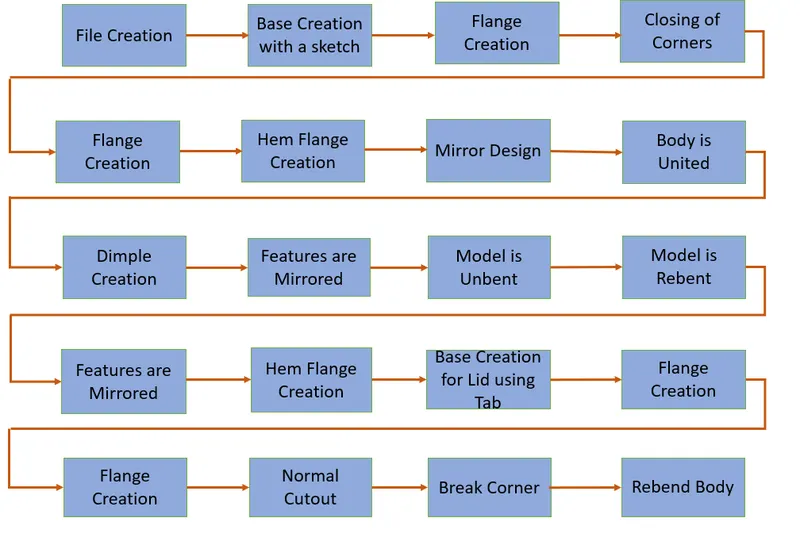
Desciption:
The description contains all the required commands that were used in the creation of this particualr model:
1. Tab: The tab command is used to create the base structure with a certain thickness.
2. Flange: The flange command is used in this model to create the enclosing walls for the structure.
3. Closed Corners: The Closed Corners command is used to create smooth corners where there is a small opening created between surfaces at the corner point of the structure.
4. Hem Flange: This a command simillar to the flange command, but it is used specifically to create a hemming flange, which is a sheet getting bent at its edges so that another sheet metal can fit in the gap and thus joining the two components.
5. Mirror Body: This command is used to create a mirrored copy of the body across the required plane.
6. Unite: The unite command is used to combine the volumes of two bodies into a single body.
7. Dimple: The dimple command is used to create an indentation on the surface of the body.
8. Unbend: The unbend command is used to remove the bends in the model and create a flat body for the creation of other features.
9. Rebend: The Rebend command is used to undo what the unbend command has done and bring the model back to its original shape.
10. Bead: The Bead command is used to create a bead feature which is used strengthen the surface.
11. Break Corner: The break corner is used to smoothen out the sharp edges and to make the design manufacturable.
12. Normal Cutout: This command is used to make cutouts on the surface based on the pre-defined sketch.
Images:
The images of the model in the different views are provided below
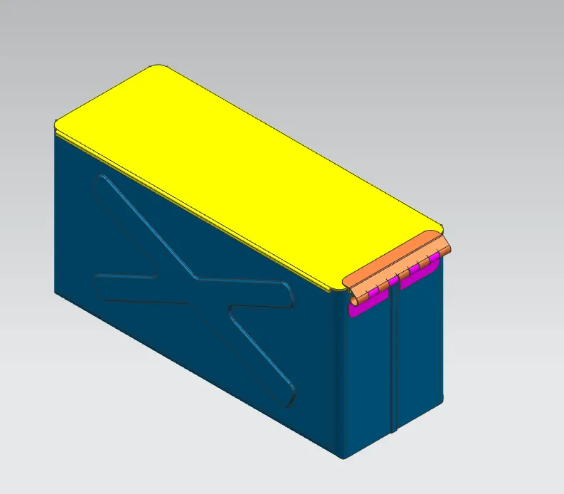
Isometric View
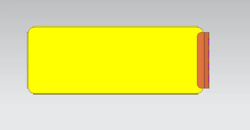
Top View
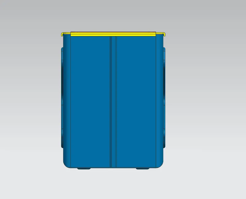
Side View (LH)
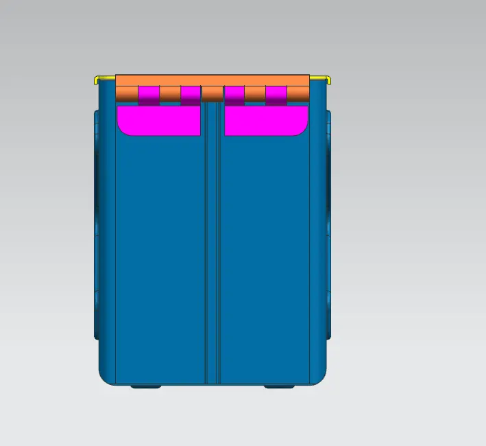
Side View (RH)
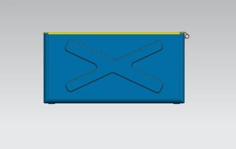
Front View
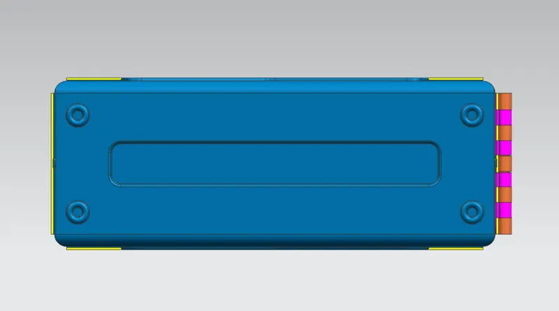
Bottom View
Conclusion:
The design was modelled as per the mandated design requirements.