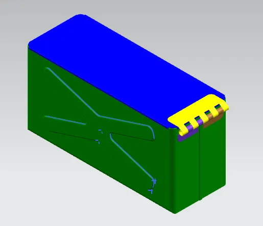
Advanced Sheet Metal Design Using NX Cad Challenge_2_Box Assembly
Title:-
Advance Sheet metal design using NX Cad Challenge 2 Box Assembly
Objective:-
To design a sheet metal Box using NX cad
Introduction:-
Sheet Metal – It is formed by an industrial process into thin, flat pieces which is mostly used in Machinery, Automotive, Aerospace, Agriculture, Mining, Shipping industry, etc. The thickness of Sheet Metal is in between 0.25 mm to 6 mm. There are many types of sheet metals available, e.g – Alloy Steel, Stainless Steel, Carbon steel, etc.
NX cad – It is normally known as “UNIGRAPHICS”. It is an advanced CAD software which is owned by Siemens. This software is used for Design, Analysis, manufacturing.
Design Methodology:-
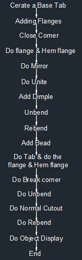
Description:-
Commands are used to complete the model:-
Sketch - By this command we can bend the tab at a particular position with reference.
Tab - By this command we can add a parameter to the 2D model.
Bend - By this command we can bend the tab at a particular position with reference.
Flange - By this command we can extend sheet metal through the edges of the tab.
Normal Cutout - By this command we can cut the model perpendicular to the sketch.
Break Corners - By this command we can round the sharp corners to avoid the manufacturing tool to stop jerk.
Unbend - By this command we can flatten the 3D model by selecting one face as a stationary face.
Hole - By this command we can create a hole on the surface of sheet metal.
Dimple - By this command we can create a particular shape by sketching with certain depth.
Hem Flange - By this command we can create a joint which is used for joining inner and outer clouser planes.
Bead - By this command we can give strength to a sheet metal at a particular shape at a certain point.
Unbend - By this command we can flatten the 3D model by selecting one face as a stationary face.
Rebend - By this command we can flatten the sheet metal.
Procedure:-
Create a rectangular block of l = 150mm, w = 200mm, t = 1mm. Then give flange 200mm & 70mm with 10mm radius and the angle of 90 degree. After that do the close corner.
Then do the flange at one side of 70mm flange, bend radius 0mm with 0.02mm length then do another flange, bend radius 0.05, with 6.5mm length and do the same operation for another side 70mm flange instate of 6.5mm length do 4,5mm length.
Then mirror the body and unite them.
Then create a rectangular and rectangular X with fillet of 10mm and do dimple of 2mm, after that mirror the rectangular X feature at another wall. Then create the circular bead at 1 corner and mirror it to the other 3 corners.
Then do unbend the box & rebend it.
Then create the hem flange 3 side of the box.
Then create a datum at 203 offset distance in XY plane, then create a tab on the outer body of the box. Then create the flange at 4 corners of the tab.
Then create a sketch at side of the box and give the dimension with break corner and do the flange and hem flange. After that do unbend and draw the sketch and do cutout and rebend it. Then mirror the body.
Then create a tab on the top side and do the break corner, after that do the flange, hem flange and unbend it. After that do the sketch and do normal cutout.
After complete the model go to edit object display and change the colour as needed.
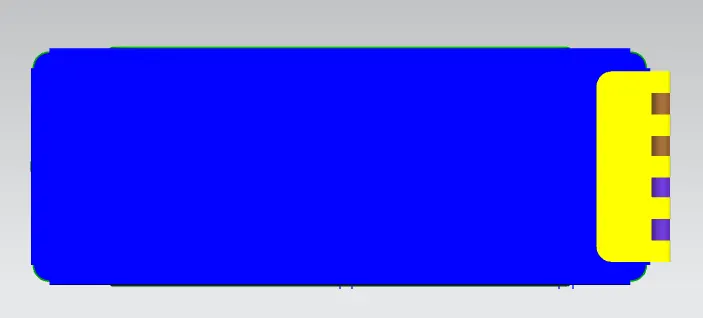
Top View:-
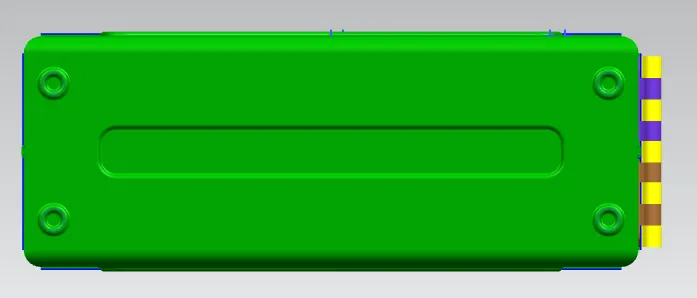
Bottom View:-
Side View:-
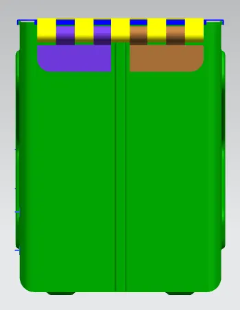
Front View:-
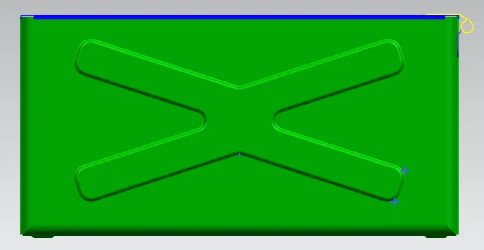
Isometric View:-