Advanced Sheet Metal Design Using NX Cad Challenge_2_Box Assembly
Box Assembly
To create 3d model of casing using NX sheet metal.
This Box Assembly has been designed using NX sheet metal and the details of the designing the Box Assembly is provided with the help of flowchart and breif explanation.
Flowchart
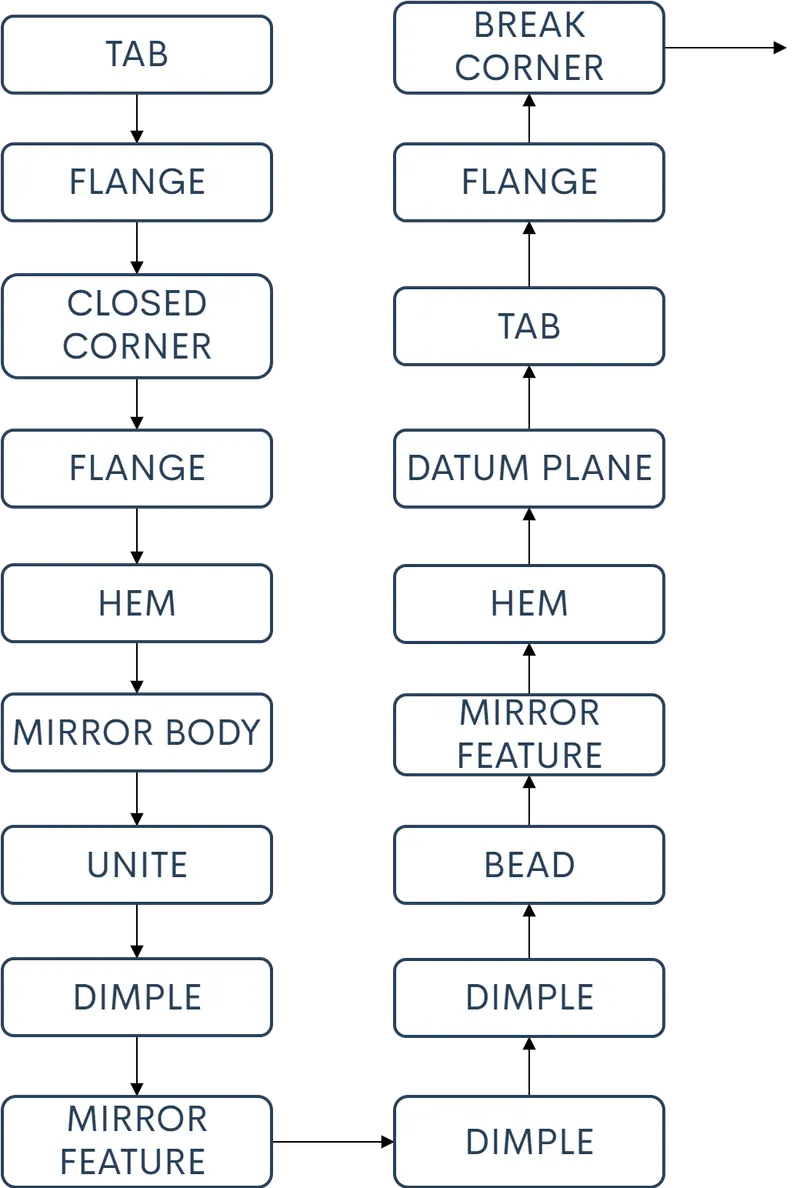
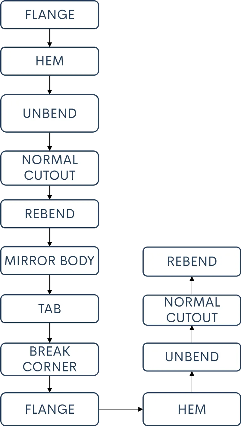
DESCRIPTION
TAB-is used to create a sheet metal extrusion from the drawn sketch
FLANGE-is used to add seetmetal extentions at the edges of the main body
CLOSED CORNER-is used to close two adjacent flanges
HEM-is used to bend the edge of the flange over itself
MIRROR BODY-is used to mirror the body to achieve symmetric model
UNITE-is used to make 2 seprate sheet metol bodies as single body
DIMPLE-is used to add the impression of the desired shape with the help of the sketch
MIRROR FEATURE-is used to mirror the features like dimple, bead....ETC
BEAD-is used to lift the material along the counter of sketch
DATUM PLANE-is used to create the new plane
BREAKING CORNERS-to eliminate the sharp edges
UNBENDING to see the shape of the sheet metal and to add other features
NORAML CUTOUT- Is used to creaye a cutout on the sheet meatal part using a sketch of desired shape
REBENDING-Is used to bend to the sheet metal part to its original shape after adding the features
ADDING FLANGES at the end of the sheet metal part to give the bend with the material
CONCLUSION
Required 3d model of the Box Assembly has been achived.