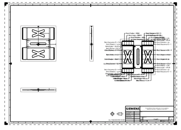
Advanced Sheet Metal Design Using NX Cad Challenge_2_Box Assembly
BOX ASSEMBLY:
INTRODUCTION:
- STRAT IN THE NX 12
- CREATE ANEW SHEET METAL model called casing part.
- create a sketch in the XY plane
- draw a rectangle centered at the origin with an x-length of 200 mm and a y width of 150mm
- exit the sketch mode.
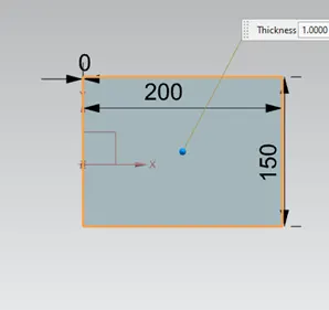
2.change design parameter.
- Go to the menu
- next step preferences
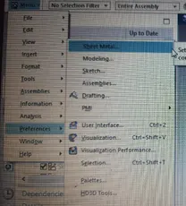
- sheet metal.
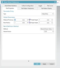
- global parameters 1mm
Adding a solid sheet.
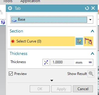
- the tab is used to sketch is converted into a thick sheet at a thickness of 1mm.
- a sketch can be created by using the tab tool also sketch is highlighted in a blue colored box.
ADDING FLANGES.
- Click on the flange command.
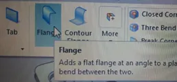
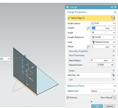
- use a length 200mm angle of 90 degrees and apply the flange on the shown edge of the metal sheet.
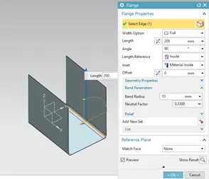
- DO the similar operation on another side provide the same values.
- do similar operations on the front and rear sides.
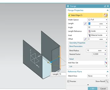
- do the same operation on the left side of the sheet metal and the same value provided.
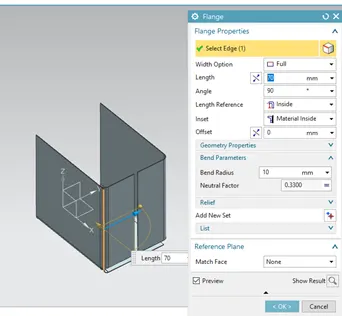
- flange open surface also provides length 0.02 and angle and 90 degrees.
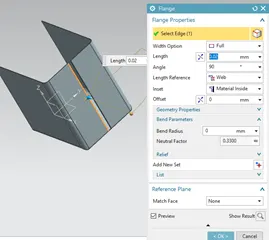
- after creating the flanges.
- do the same operation on the opposite also.
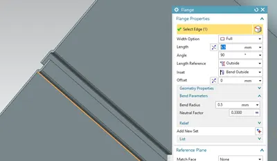
- after creating the flanges create on the flange at the length of 6.5 mm angle 90 degrees.
CLOSE CORNERS:
- Select the close corner command
- go with the close and relief corners.
- at the gap of 0mm.
- treatment at the close.
- overlap close select.
- select the blend.
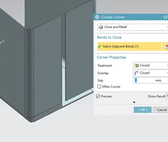
- use a similar operation on another side.
APPLYING HEM :
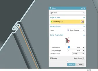
- Select hem command
- selects the corner give the length 3mm radius 0.5mm.
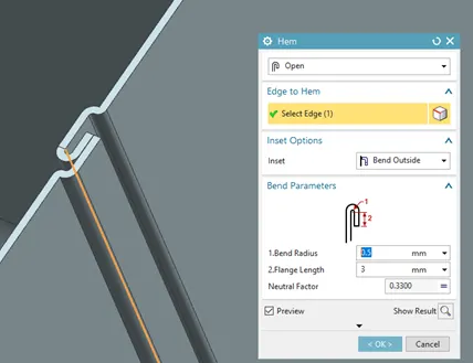
- do a similar operation on the opposite side.
MIRROR:
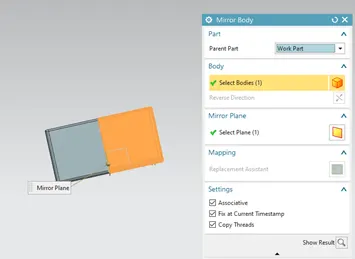
- Select the mirror body command
- to select the body and required plane.
- make sure in settings click the fix at the current timestamp
- shows in the below figure.
UNITED:
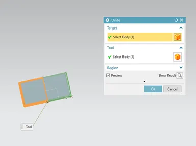
- SELECT THE TWO BODIES TO JOIN.
DIMPLE:
- BY USING THE DIMPLE COMMAND
- create the sketch and on the metal surface.
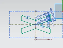
- set the depth option to 1mm and sidewalls to material inside.
- expand the rounding field by left-clicking on it.
- set all the parameters of the rounding field to 1mm.
- click ok.
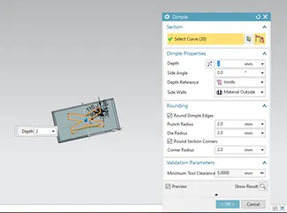
- do the same operation on another side.
- by projecting a sketch on the opposite side.
- do a similar operation on the bottom of the box.
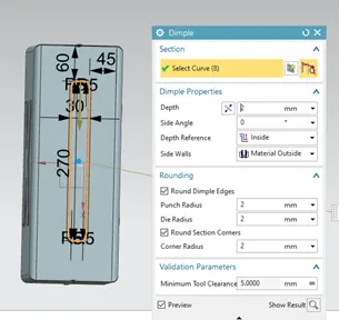
TOP SURFACE OF THE BOX:
- create the sketch on the surface by using the datum plane.
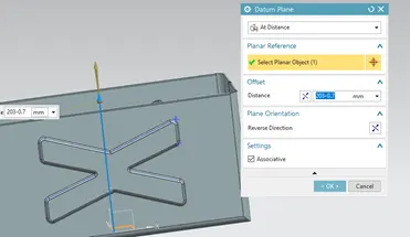
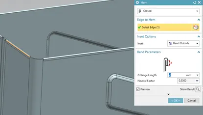
APPLYING HEM:
- APPLY THE HEM ON THE CONER OF THE BOX.
- Do a similar operation on the required corners.
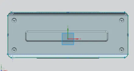
- created the sketch by using the respective datum plane.
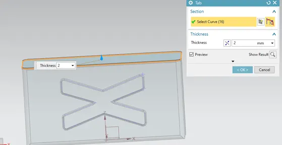
- by using the tab add thickness to the sheet metal.
- add flanges at the sides of the surface.
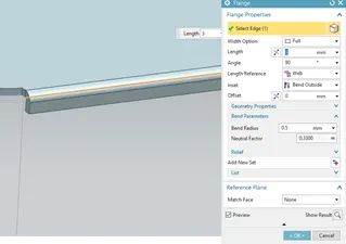
- similarly, add the same operation on another side.
- create the sketch on the front side of the box.
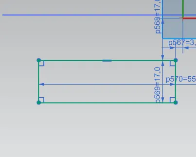
- use the tab command to create the sheet.
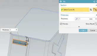
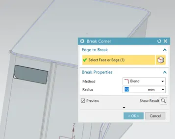
USE THE BREAK CORNER COMMAND :
- use the remove to a sharp corner.
- at the radius of 10 mm
CREATE THE FLANGE ON THE TAB SURFACE :
- Select the edge
- to provide the 4mm and angle 40 degrees.
- bending radius is 0.5mm.
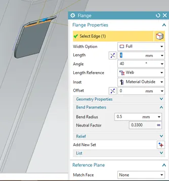
- do the same operation on the flange.
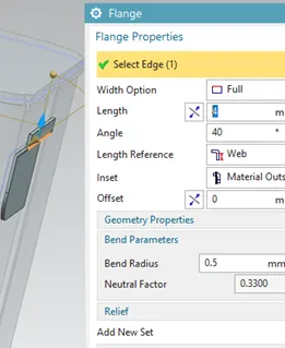
- applying the hem:
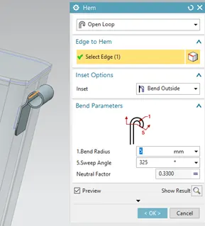
- apply hem on the flange
- go with the open-loop and select the edge.
- and bend outside.
- provide bend radius 5mm
- sweep angle 325mm.
- and unbend it and create the sketch on it
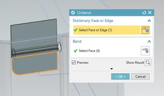
- sketch on the surface
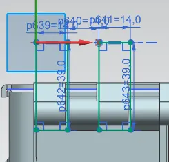
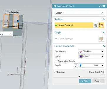
- use Normal cut-out the surface.
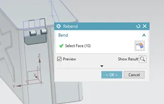
REBEND the surface.
- by using the re bend command take them into their original position.
- by using the mirror body.
- mirror it on another side.
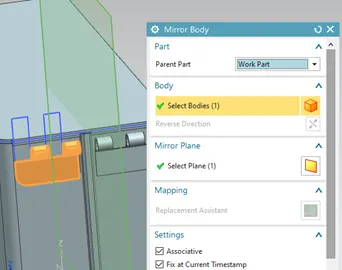
- do a similar operation on the top.
BEADS:
- FIRST CREATE THE SKETCH.
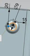
- by using the bead command
- in the bead dialog box select the circle you have just drawn.
- set the depth and radius to 2mmand the cross-section to circular.
- the die radius to 2mm.
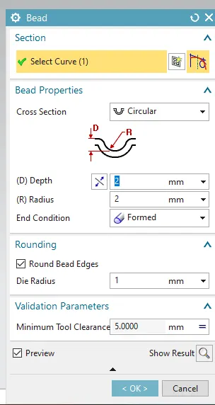
- by using the mirror feature
- select the bead and its corresponding sketch as a feature to mirror.
- do the same operation to another side.
- The flat pattern command is used to create the flat pattern.
DRAFTING:
- go to the application and select the drafting.
- Select the new page and required size like A3.
- then select the base view
- to adjust the sheet metal view like top view, front view.
- for the moment, the flattened version is not visible .to make it visible, go in the part navigator and expand the model and model tree.
- in the base