Advanced Sheet Metal Design Using NX Cad Challenge_2_Box Assembly
SHEET METAL DESIGNING OF A BOX ASSEMBLY OBJECTIVE
AIM: The objective of the project is to design a box assembly using the sheet metal application in nx cad software
INTRODUCTION
Sheet metal is metal formed by an industrial process into thin, flat pieces. sheet metal is one of the fundamental forms used in metalworking and it can be cut and bent into various shapes
BOX ASSEMBLY is created in order to understand the basics of sheet metal application in siemens nx .
DESIGN METHODOLOGY
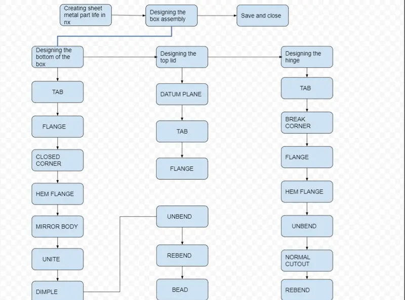
FEATURE USED TO CREATE BOX ASSEMBLY
- TAB: Creates a base feature by extruding a sketch along a vector by thickness value or adds material to a planer face. An additional planer section can be added to generate bends as part of the feature.
- NORMAL CUTOUT: cuts material by projecting a sketch onto the model and then cutting perpendicular to the faces intersected by the projection
- BEND: modifies the model by bending material on one side of the sketch line, adding a bend between the two sides.
- FLANGE: adds a flat flange at an angle to a planer face and adds a bend between the two
- BREAK CORNER: Rounds or chamfer a sharp corner of Tab or flange
- UNBEND: Flattens a bend and the material adjacent to bend
- MIRROR: copies a feature or body and mirrors it across a selected plane
- HOLE: adds a hole to one or multiple positions on a solid body
- DIMPLE: it simulates a stamping tool by lifting an area of the model
- BEAD: it stimulates a stamping tool by lifting material along a contour of sketch
- REBEND: restores an unbend feature to its previous state
- FLAT PATTERN: creates a flat pattern from the formed sheet metal part
STANDARD VIEWS OF THE BOX ASSEMBLY
1. FRONT VIEW
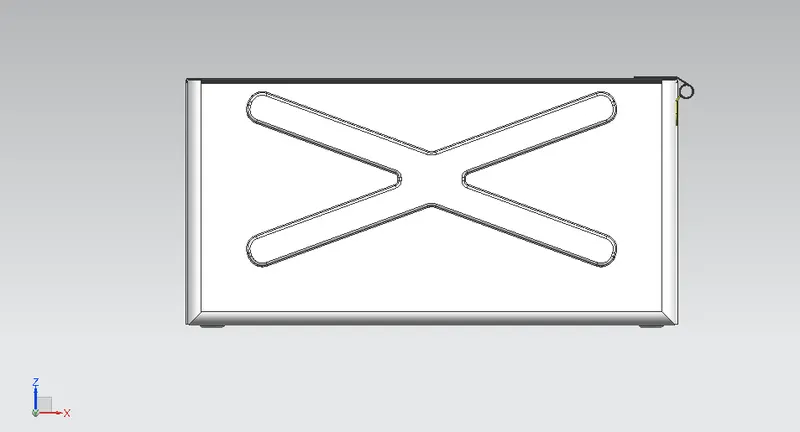
2.SIDE VIEW
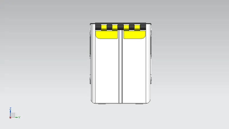
3.ISOMETRIC VIEW
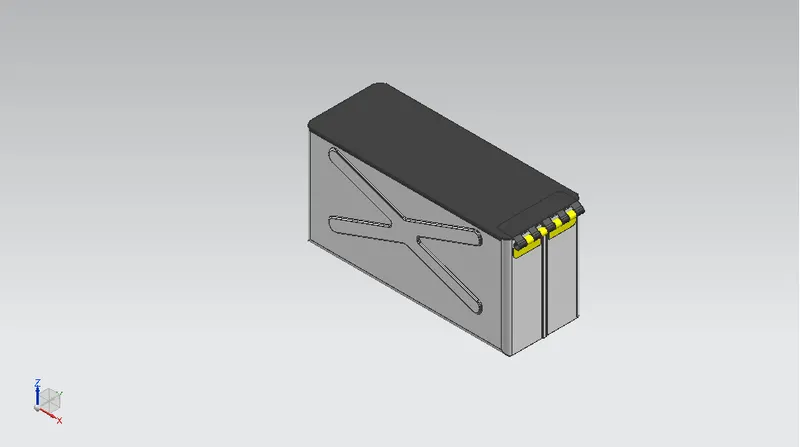
4.TOP VIEW
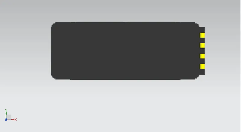
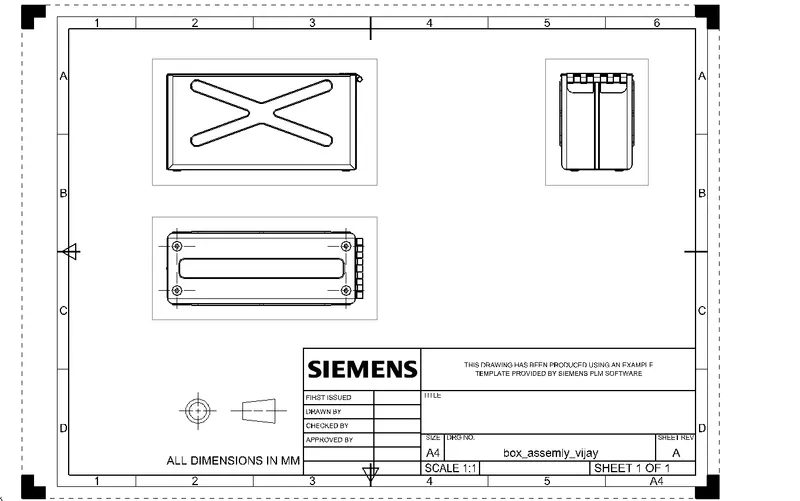
5.DRAWING SHEET BOX ASSEMBLY
CONCLUSION :
THUS THE PROJECT HAS BEEN COMPLETED BY DESIGNING A SHEET METAL BOX ASSEMBLY USING THE SHEET METAL APPLICATION IN NX