Advanced Sheet Metal Design Using NX Cad Challenge_1_Casing Design
CASING DESIGN USING NX CAD
OBJECTIVE
- To design a sheet metal casing using NX Cad with suitable commands and create Drawing Sheet of final model.
INTRODUCTION
- Sheet metal is metal formed into thin, flat pieces, usually by an industrial process.
- Sheet metal is one of the fundamental forms used in metalworking, and it can be cut and bent into a variety of shapes.
- Thicknesses can vary significantly; extremely thin sheets are considered foil or leaf, and pieces thicker than 6 mm (0.25 in) are considered plate, such as plate steel, a class of structural steel.
- Sheet metal is available in flat pieces or coiled strips.
- The coils are formed by running a continuous sheet of metal through a roll slitter.
- In most of the world, sheet metal thickness is consistently specified in millimeters.
- In the U.S., the thickness of sheet metal is commonly specified by a traditional, non-linear measure known as its gauge.
- The larger the gauge number, the thinner the metal. Commonly used steel sheet metal ranges from 30 gauge to about 7 gauge.
- Gauge differs between ferrous (iron-based) metals and nonferrous metals such as aluminum or copper. Copper thickness, for example, is measured in ounces, representing the weight of copper contained in an area of one square foot. Parts manufactured from sheet metal must maintain a uniform thickness for ideal results.
- There are many different metals that can be made into sheet metal, such as aluminium, brass, copper, steel, tin, nickel and titanium.
- For decorative uses, some important sheet metals include silver, gold, and platinum (platinum sheet metal is also utilized as a catalyst).
- Sheet metal is used in automobile and truck (lorry) bodies, major appliances, airplane fuselages and wings, tinplate for tin cans, roofing for buildings (architecture), and many other applications.
- Sheet metal of iron and other materials with high magnetic permeability, also known as laminated steel cores, has applications in transformers and electric machines.
- Historically, an important use of sheet metal was in plate armor worn by cavalry, and sheet metal continues to have many decorative uses, including in horse tack.
- Sheet metal workers are also known as "tin bashers" (or "tin knockers"), a name derived from the hammering of panel seams when installing tin roofs.
DESIGN METHODOLOGY
Strat the Nx and create a new sheet metal model.
↓
Create a sketch on XY Plane with 60X50 mm dimension
↓
Set default values in Menu>Preference>Sheet metal.
↓
Follow the instruction in the PDF to form the Base feature’s profile
↓
Apply Bends on the Base feature
↓
Use Break Corner command to round the sharp corners
↓
Unbend the sheet metal product
↓
Add size M2 holes on the middle of the flanges
↓
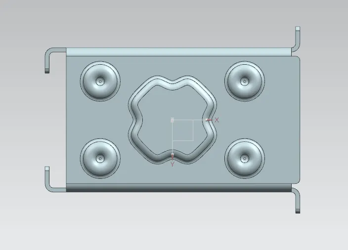
Add the Dimple and Beads on the body using sketches as reference
↓
Re-Bend the Metal Sheet
↓
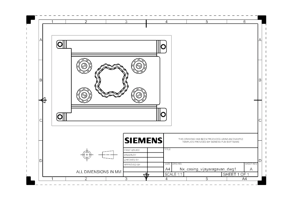
Create the Drafting of the product in a new Drawing
Descriptions
The important tools used in the design procedures are:
1. Sketch Helps to draw profiles for the different tools to use on.
Studio Spline Creates a spline through all selected points.
Move Curve Can move a created curve according to selected references by provided given distance/angle.
Mirror Curve mirrors the drawing in the sketch with respect to an axis/plane.
2.Tab Creates a base feature by extruding a sketch along a vector. The thickness and material data can be provided.
3.Normal Cutout Cuts the base feature/part perpendicularly with reference to a sketch/profile provided.
4.Bend Modifies the base by bending it with a reference flat surface and a sketch line to depict the bend.
5.Flange Adds flanges to the edges selected. Angle between main surface and length of the flange can be provided.
6.Break Corner Smoothens all selected sharp corners. It fillets the corners with the provided radius.
7.Unbend Flattens the created 3D sheet metal part into a 2D part.
8.Hole Used to create specific types of holes for screws. The threading, boring, etc can be provided separately.
9.Dimple Lifts/ creates a depression on the material along a sketch. It stimulates stamping process.
10.Bead Lifts the material along a sketch, this also stimulates a stamping operation.
11.Rebend Restores the bends on the selected faces of the created feature.
12.Flat Pattern Creates a flat pattern of the feature with all the information on the dimensions.
13.Drawing It’s used to create drafted drawings of selected part/product.
- Base View creates the main view on the drawing sheet.
- View Creation Wizard helps to create customized view of the selected product.
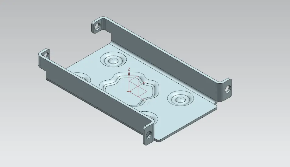
Isometric View:
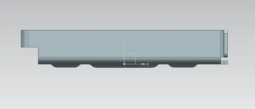
Front View:
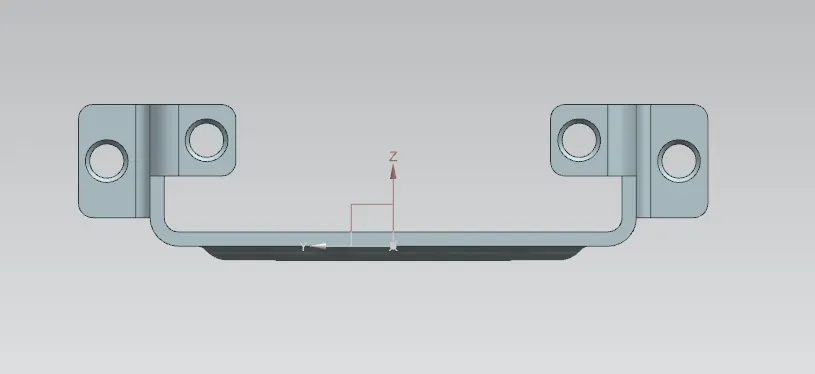
Side View (Left):
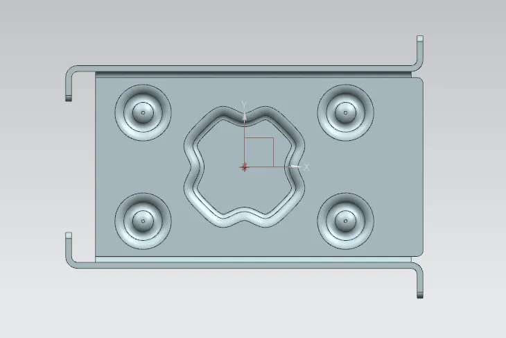
Top View:
Back View:
Detailed Drawing:
Conclusion
- The Sheet Metal Casing is Designed using Siemens NX CAD software and the drawing of the product is made.