Advanced Sheet Metal Design Using NX Cad Challenge_1_Casing Design
Title :-Advanced sheet Metal Design
Objective: To create casing using various features of sheet metal
Introduction:
Crated new model in the NX cad and named it as casing.part.
Go to sketch and then draw a rectangle in xy plane centered at the origin with length 60mm and width 50mm exit that sketch mode.
Now we need to do some settings to modify thickness of tab or rectangle while extruding .
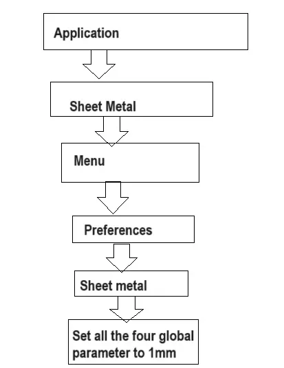
Go to Ribbon bar there is Tab feature through which we can extrude sketch by given value.
Go to Tab button to create first rectangular metal sheet of 1mm thickness.
Create a new sketch in plane P containing upper face of the rectangular sheet and parallel to the xy plane.
In that sketch draw a rectangle which is symmetric with respective x axis which is coincident with the left edge of the rectangular metal sheet .the rectangle is 5mm wide and 40mm long.
Now exit a sketch mode to use Normal cut out button to make rectangular hole ln the sheet.
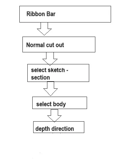
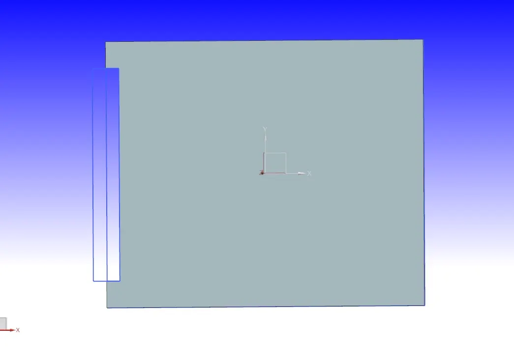
Bending:
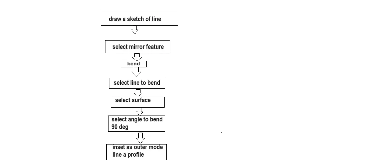
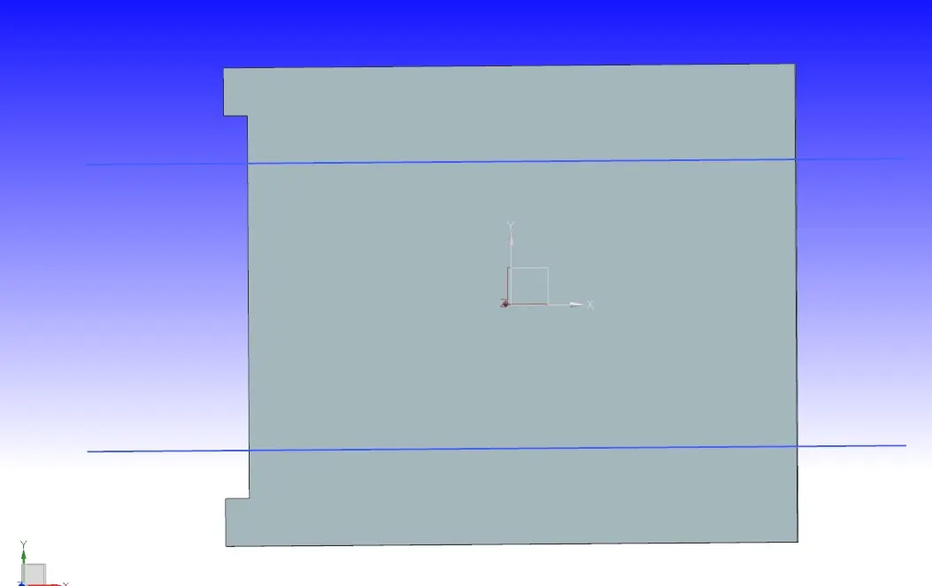
Again draw a sketch in plane P and consisting two horizontal symmetric lines with respective axis X.
Go to sketch select plane P draw a horizontal line then go to in a ribbon bar there are certain sketch features take a line option form this and draw a line of arbitrary length then get out of sketch and go to more option form ribbon bar and select mirror feature option then select feature to mirror as a line and plane.
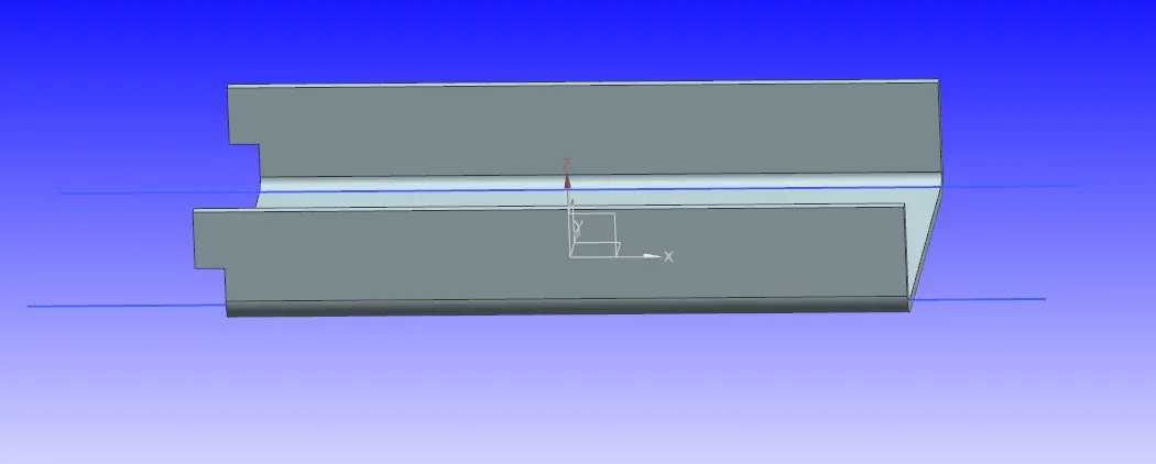
Then go to more first and select bend option form select curve as line select face as tab and angle as 90 deg by which have to bend this tab and inset as outer mode line profile.
Repeat the bend command twice to get expected result.
Adding Flanges:
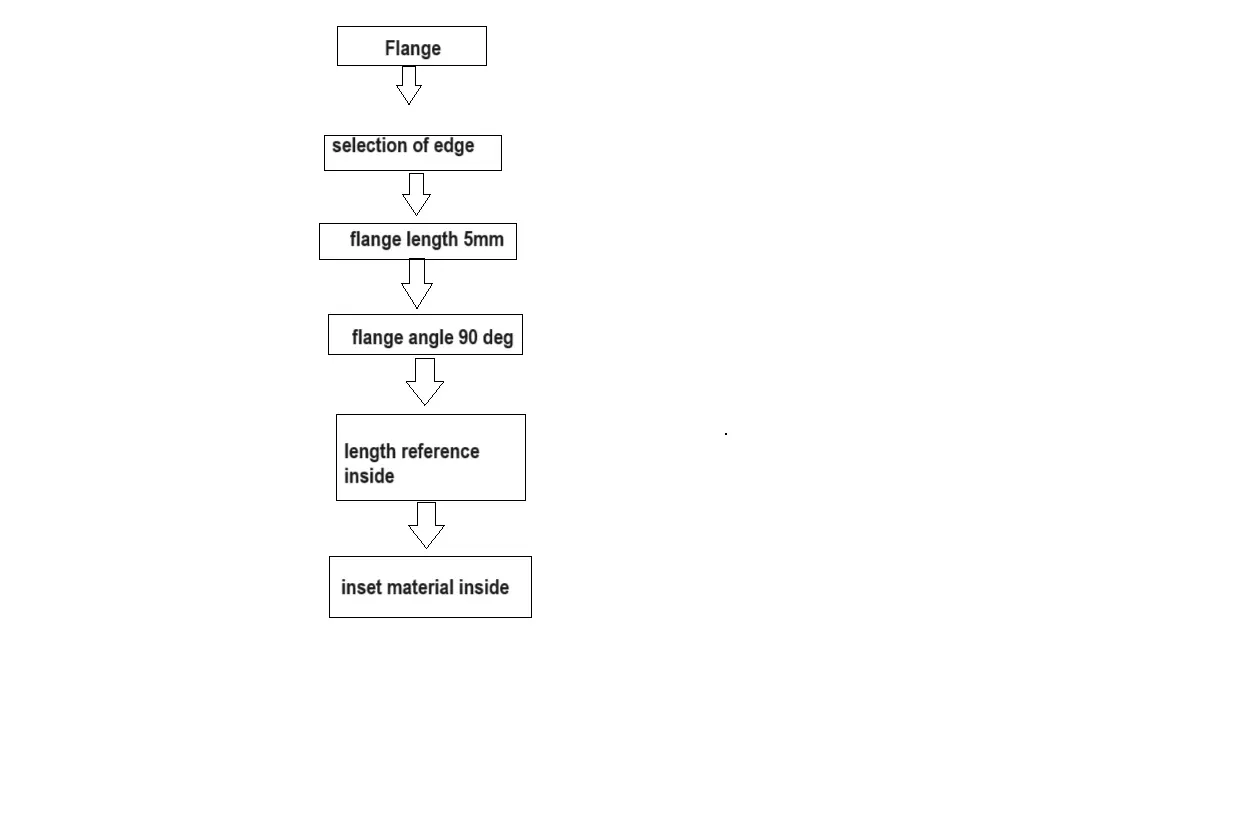
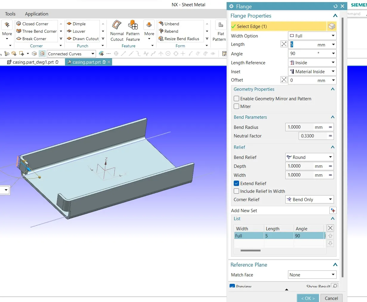
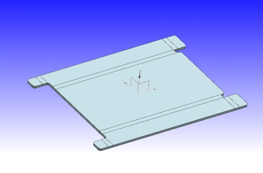
There is flange feature in ribbon bar select that button and select external edges to be flange and set with option full,angle 90 deg,flange length 5mm,length reference inside and inset material inside.same as first select other edges also.
Breaking Corners:-
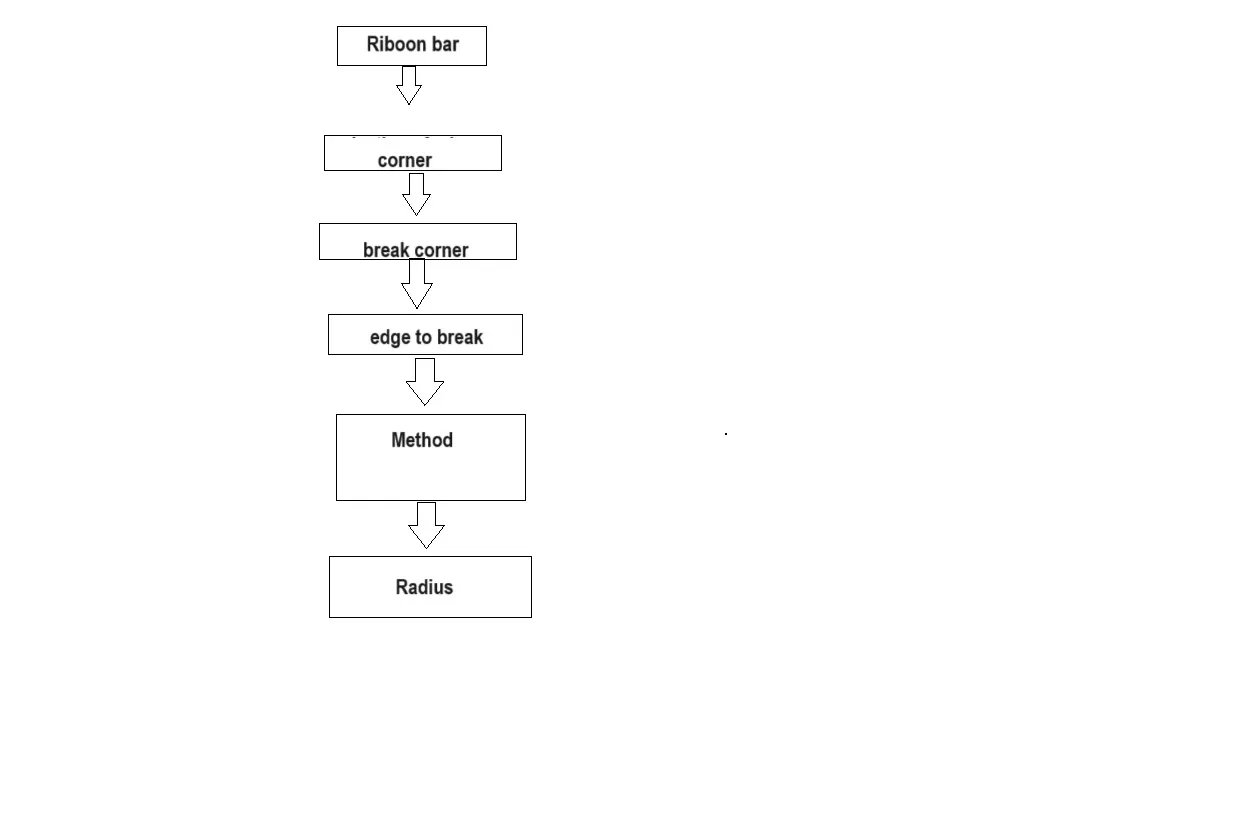
In Ribbon bar there is corner option where is break corner button click on it ,select edges to break next in break properties method is bend and radius 1mm.
Unbending:-
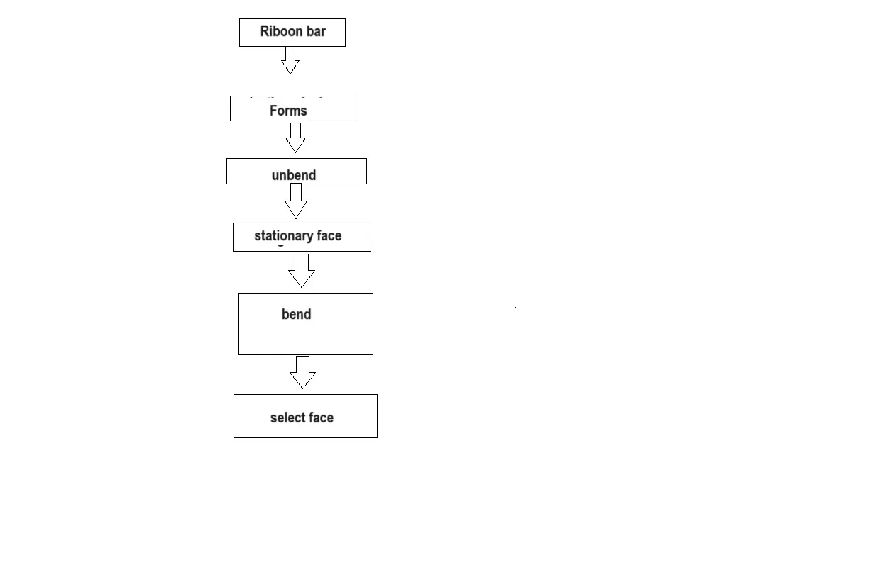
To the ribbon bar there is Form option in that unbend option is placed click that option,select stationary face or edge,select face or edge then Bend select face ticked on exact gusset curves.then ok.
Adding Holes:
Figure out four points which indicates center of holes,
Go to sketch plane in metal sheet in lower part of the metal sheet draw a line whoes extremities are located on middle of the flanges that had drawn.
Draw a point on the center of the line and form that point draw symmetric point w.r.t. of XZ plane and also YZ plane.
To draw symmetrical points go to Ribbon bar there is direct sketch Box in that box there is line option and point option use them to draw point and line respectively and then use mirror image option from same and mirror that points along XZ and YZ planes.
Hole Feature :
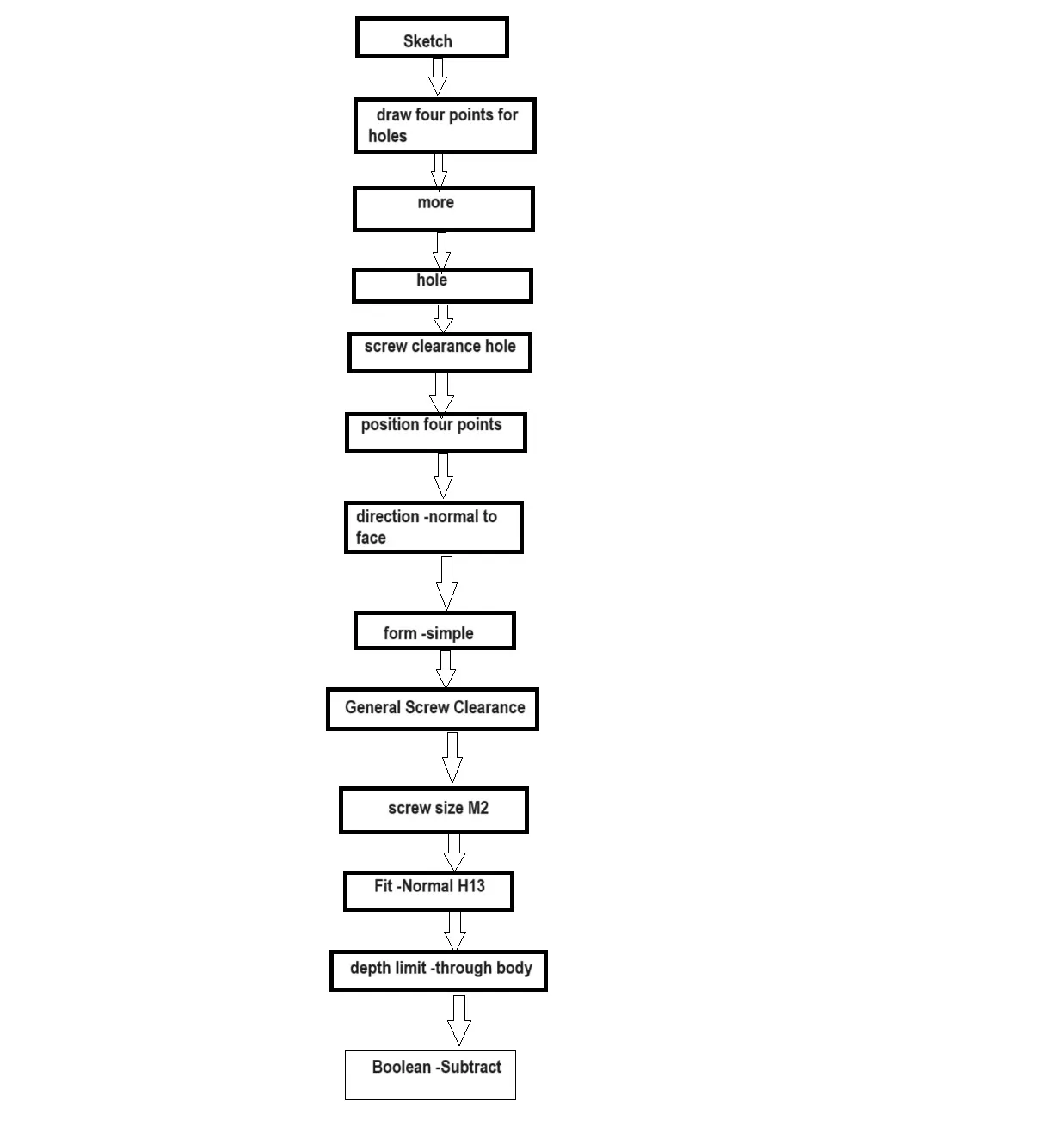
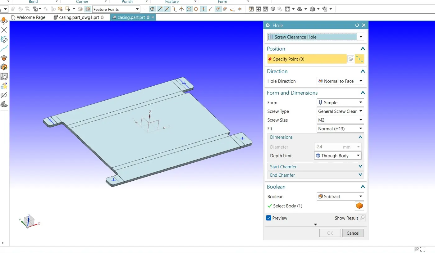
We are using hole feature to create hole in the metal sheet .
Go to ribbon bar there is More second option there are some design feature take from them hole and hole type screw clearance hole then position specify four points and then direction -hole direction normal to the face Form and Dimension from simple screw type general screw clearance and screw size M2 and fit normal H13 depth limit through body and boolean operation subtract.
Adding a dimple:
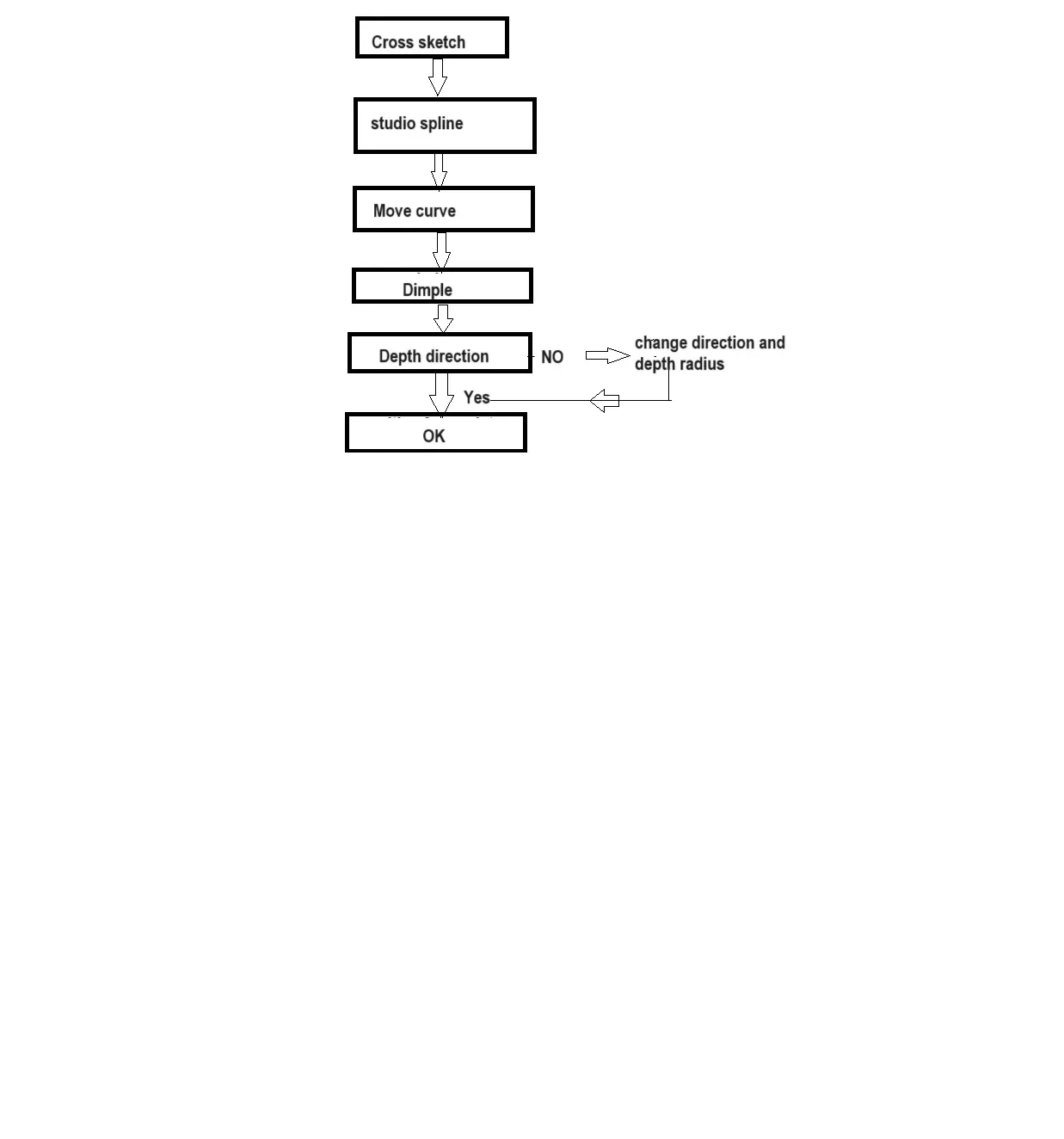
Go to sketch and draw a plus sign (Cross Sketch)with origin as center in XY Plane and each half side is 5mm in length.
There is studio spine option in direct sketch select it then select type By Pole and specify poles as 16 points at either direction,parameterize ‘close ‘ and degree ‘3’ Movement ‘View’ OK.
Now we have to rotate this curve/spline by an angle of 45 deg.
Go to Move curve option in curve tick on use curve finder and select curve for this as spline and set angle 45 through Transform -Motion -Angle specify axis point origin and Angle -45.
Get out of sketch
Dimple: -
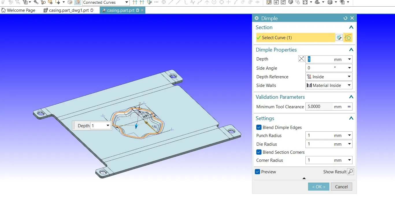
In Ribbon Bar there is Groups select Punch through them and select Dimple.
Section select curve ,
Dimple properties -Depth 1mm,Side Angle zero ,Depth Reference inside ,Side Wall Material Inside.
Bend dimple edges -Punch radius-1mm, Die Radius 1mm,Blend Section Corners-Corner Radius-1mm.
Adding Beads:
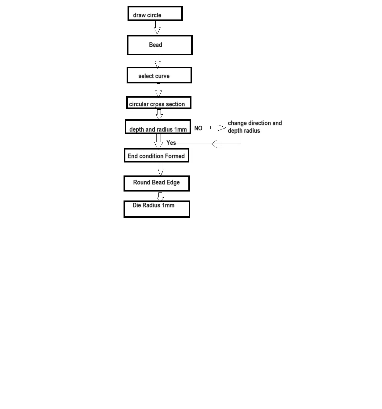
In XY Plane draw a Sketch of circle of 5mm in diameter centered at (8,8) Exit Sketch.
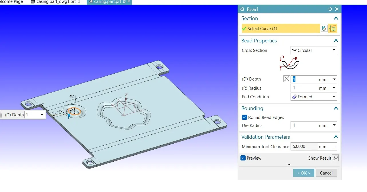
Ribbon bar there is Box of punch through which select Bead option.
Section -select curve (Circle),Bead Properties -Cross Section Circular,Depth 1mm,Radius 1mm,End condition Formed.
Rounding -Round bead Edges,Die Radius 1mm,OK.
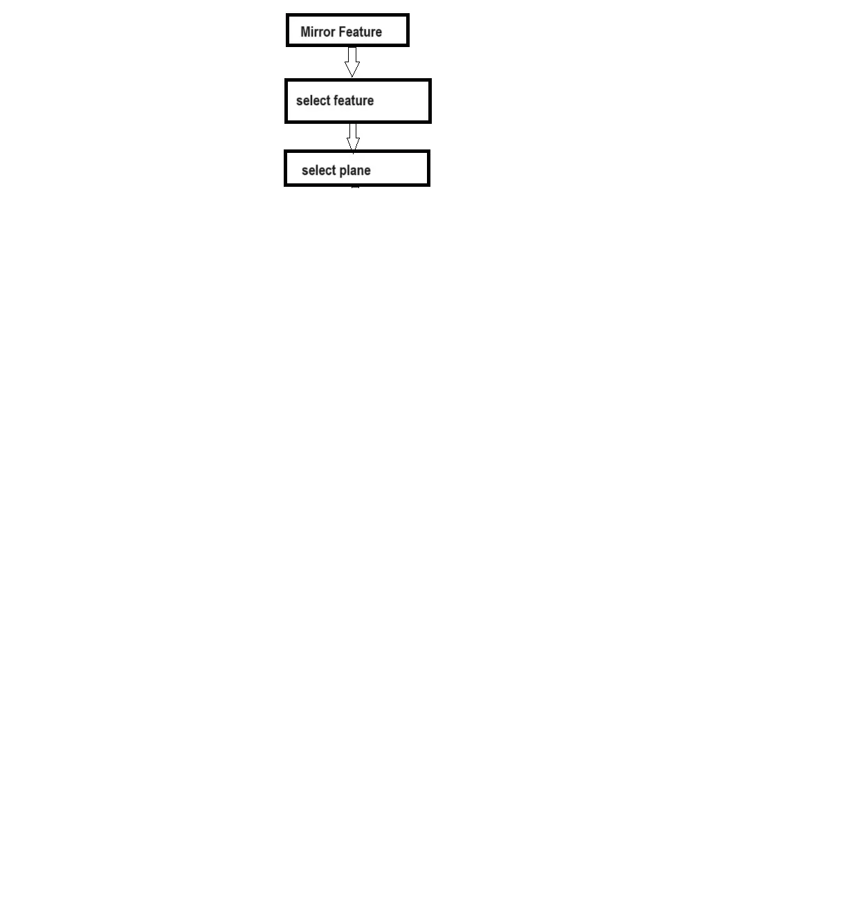
Use mirror feature to symmetry this circle on other side by selecting planes XZ and YZ
Mirror Feature:
Select more second option and select mirror feature and then select select feature as circle and select plane XY and XZ alternately.
Re bending :
Click on the Re-bend button -and select them in them in reverse order in which they where bend.
Drafting :-
Select Flat Pattern feature from ribbon bar and select upward face of casing click OK.
Now Create new Drafting file A4 size from file-new file save it to same folder as saved part file.
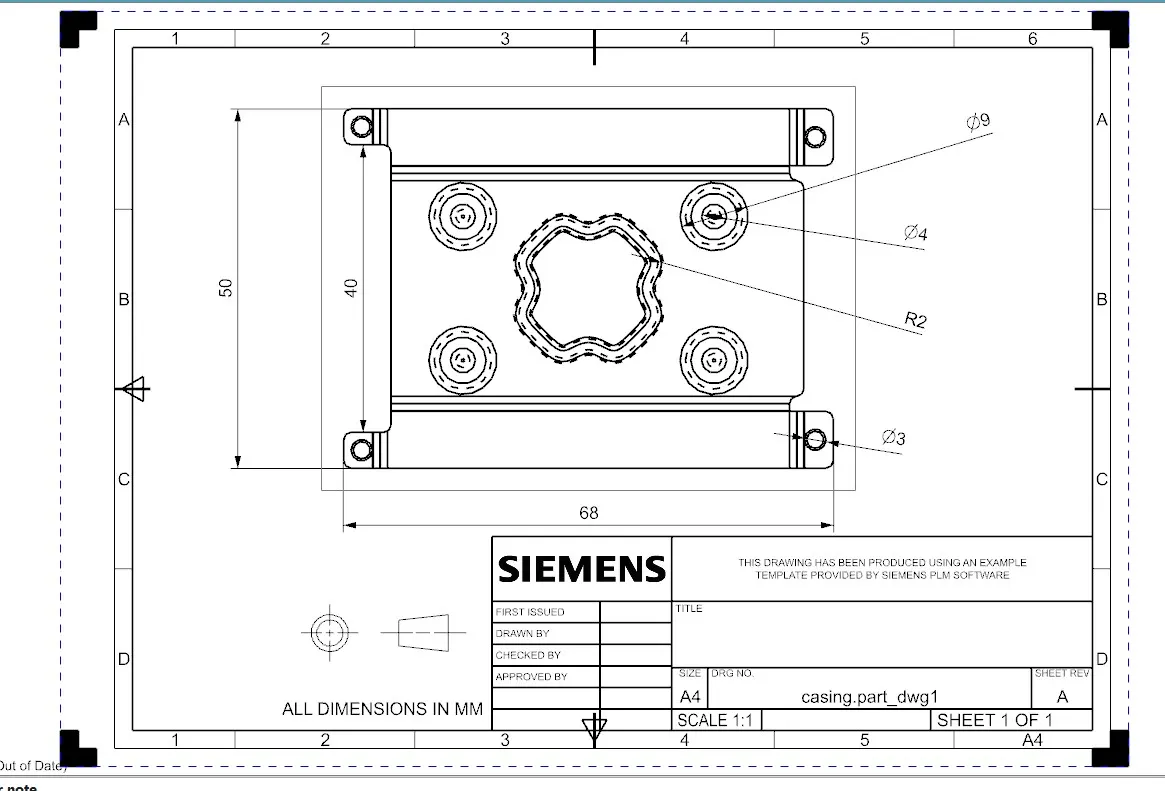
To the ribbon bar -view box-select base view through that.select central flat face of the metal sheet and validate it ,will create flatten version of out metal sheet click OK if information dialog box opens select ratio as 2:1 if required.
Conclusion : Can perform various operations on metal sheet by using features of sheet metal .