Advanced Sheet Metal Design Using NX Cad Challenge_1_Casing Design
CASING
OBJECTIVE:
To create the casing in NX sheet metal by using the given Sketch and procedures.
INTRODUCTION:
Using the advanced tools of NX sheet metal we have to create the casing with the given sketch.
Here we are going to use the following tools to create the required part.
- Sketch - Used to draw required shapes.
- Tab - The base feature created using the sketch with the required thickness.
- Normal Cutout - Create the cutout in a sheet metal using a sketch.
- Bend - Used to bend the tab with a line.
- Flange - It is created by using the edges of a tab or flange. It contains both web and bend region
- Holes - These are created directly by using points.
- Break Corner - Using this command we can blend the sharp corners.
- Dimple - It is used to lift an area of a model using a sketch.
- Bead - These are created to strengthen the part by using the sketch.
- Unbend - Using this we can unbend the bended regions.
- Rebend - We can also rebend those unbend areas.
- Flat Pattern - This command is used to give a 2D projection of the flattened sheet metal.
METHODOLOGY:
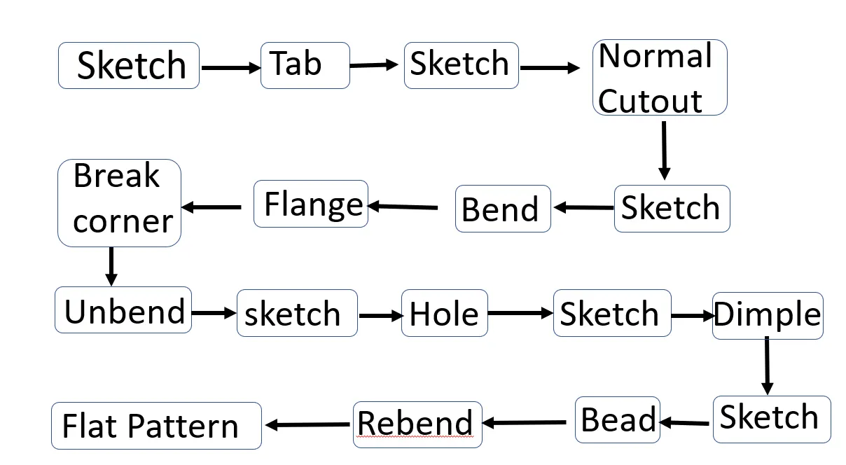
DESCRIPTION:
Open a new sheet metal part for working.
Create a sketch in the XY plane with the given dimensions.
Set the preferences to 1mm.
create the tab by using the global value.
Use the normal cutout we have to create a cutout.
Draw the sketch within the normal cutout.
once we finish the sketch we have to give depth to the cutout.
Use the sketch in the bend option to draw a line at a distance of 10 mm.
Finish the sketch and bend the tab.
Do the same on the other side and bend it on the other side.
Using the flange command create a flange using the edges.
The flange is of 5mm length.
Use the break corner command to blend the sharp edges at 1mm.
Unbend the part by giving the large rectangular face as the base and give all the bend areas.
Create a Sketch on the XY plane and draw points on the flanges for hole creation.
By using the hole command create the holes with the points.
The hole must be a screw clearance hole with M2 and the depth of desired distance.
Create a sketch on the XY plane
The spline is created by poles by selecting the 16 poles.
Move the curve using the angle at 45 degrees with the origin.
Create the dimple using the spline.
Create a sketch using the XY plane.
Create four circles at a specified distance.
Using the circles to create the bead a specified direction as given in the diagram.
Rebend the given part back to position.
Create a flat pattern using the part and it is a 2D model of the Flat solid.
Views:
Isometric View:
Front View:
Side View:
Top View:
Drawing Sheet :
Conclusion:
We have created the Casing with the given Drawing and procedure using NX sheet metal tools.
Thus the given casing from sketch to flat pattern is created and the drafting is also attached to the part.