Advanced Sheet Metal Design Using NX Cad Challenge_1_Casing Design
ADVANCED SHEETMETAL DESIGN OF CASING USING NXCAD
OBJECTIVE: To create a casing in sheetmetal module using NX CAD commands
INTRODUCTION:
Sheet Metal Fabrication is the process of forming parts from a metal sheet by punching, cutting, stamping, and bending. 3D CAD files are converted into machine code, which controls a machine to precisely cut and form the sheets into the final part. Sheet metal is generally used in automobiles, airplane fuselages, wings, and also in utensils. To manufacture all these in different designs and preparing drafting in the desired way by a manual drawing cannot be performed. If we use the design tools to do this can be a better choice and helps in modeling the object can be done easily. There are some of the design tool software are available like CATIA, AUTOCAD, NX CAD, SOLID WORKS, CREO, etc. I have designed the casing using NXCAD
DESIGN METHODOLOGY
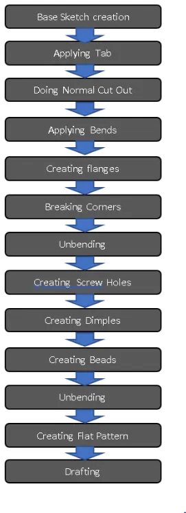
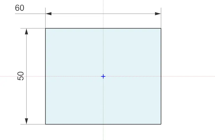
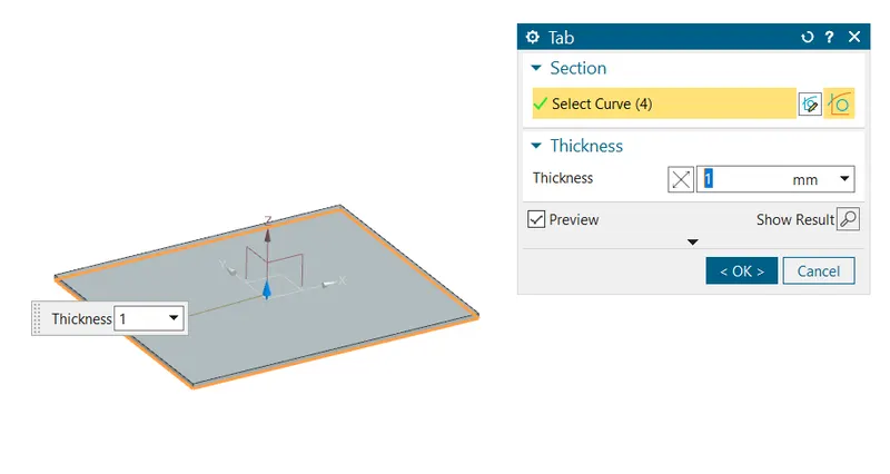
Base sketch creation and creation of tab
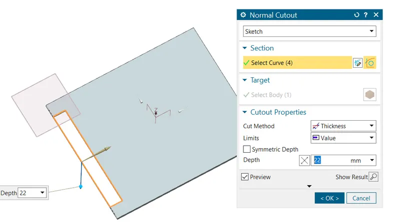
Normal cutout
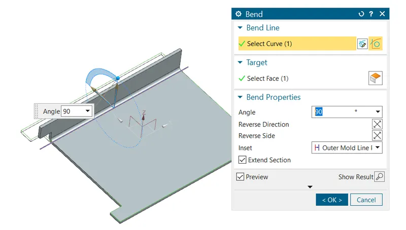
Bend
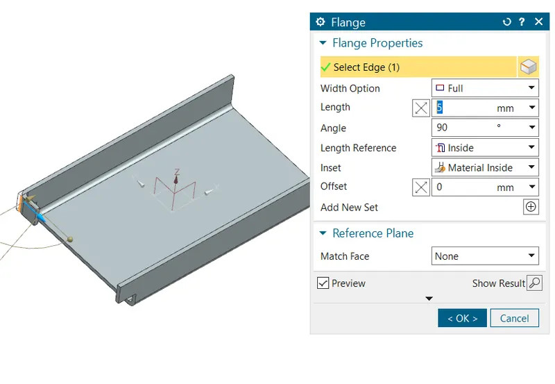
Flanges
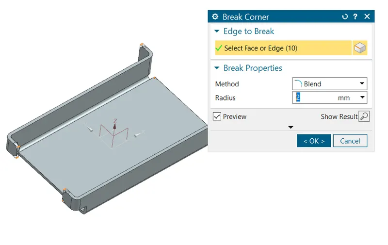
Breaking corners
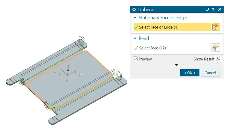
Unbending
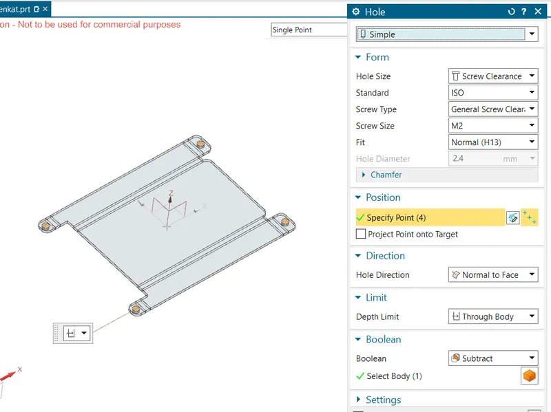
Holes for screws
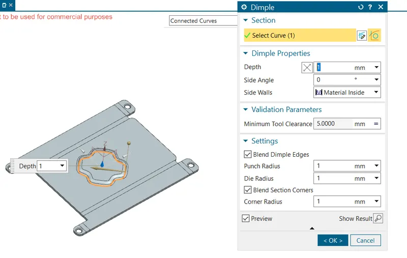
Dimple
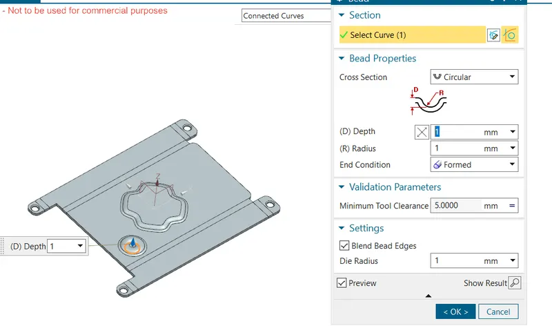
Beads
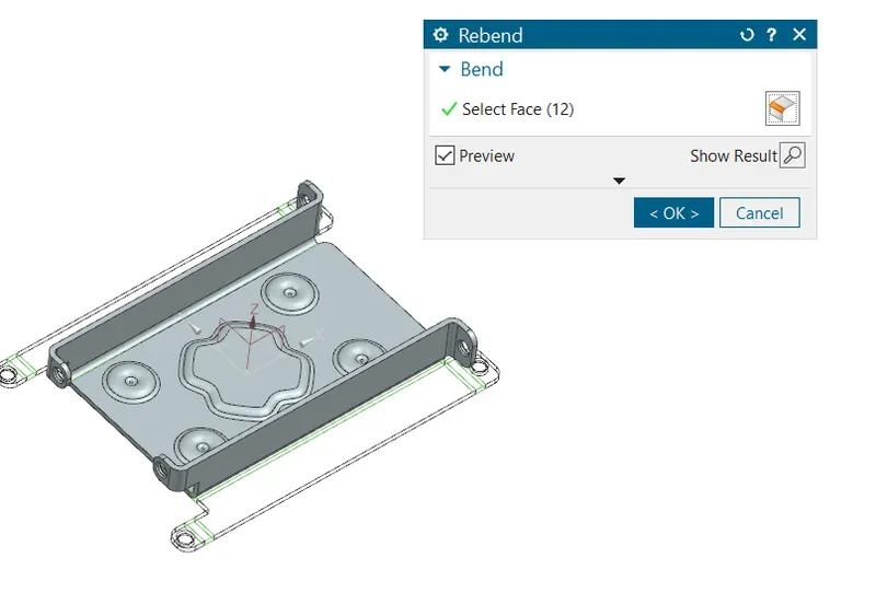
Unbending
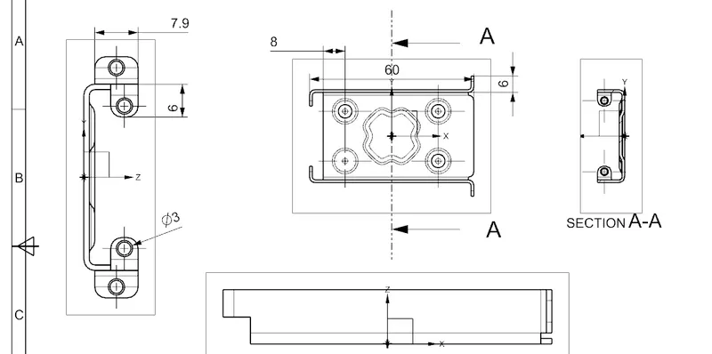
DRAWING SHEET
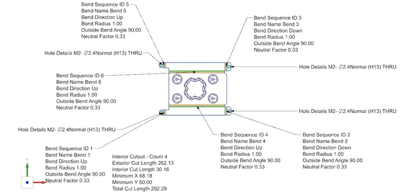
FLAT PATTERN
FEATURES/TOOLS
1. TAB: This feature is used to create a base tab on selecting the curve drawn in sketch mode with the appropriate thickness on our desire and it can easily convert that sketch into the sheet.
2. NORMAL CUTOUT: This feature is used to cut the portions of the sheet metal by assigning sketch curves.
3. BEND: This feature is used to bend the sheet metal along the sketched curve upon our requirement.
4. FLANGE: Flange is used to add flanges on selecting the edges of our sheet metal, it is working as a BEND feature along with that extra material can be added by adjusting the length of the flange.
5. BREAK CORNERS: Break corners are used to make the edges round for easy handling when using.
6. UNBEND: Unbend is a feature used to analyze the model whether a part was perfectly assigned the features, which ensures for a modeler to do further operations on it.
7. HOLE: It is actually used for making the holes on the requirement for further assembly of the part by assigning different types of specifications of screws.
8. DIMPLE: It is used to draw a dimple on selecting a curve for modeling the sheet.
9. BEADS: This feature is used to create a bead on the sheet which generally strengthens it.
10. MIRROR: It is used to add the material or feature replicates by acting as a mirror to it, this generally reduces the modeling time.
11. REBEND: This is used to re-bend the object after all conformations and ready for production.
12. DRAFTING: It is used to provide the dimensions and views of the designed part to the manufacturing team.
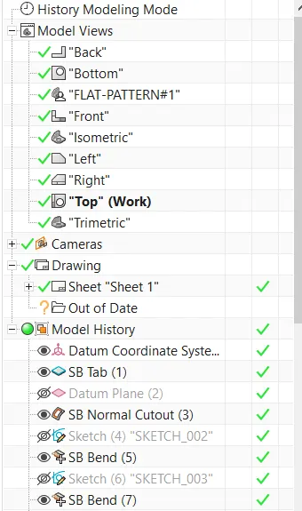
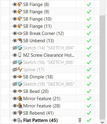
MODEL TREE:
ORIENTATIONS OF CASING
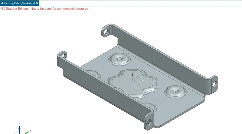
Isometric view
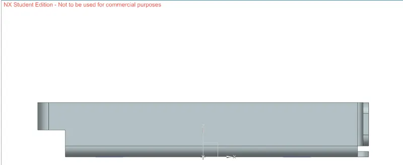
Front view
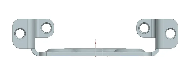
Side view
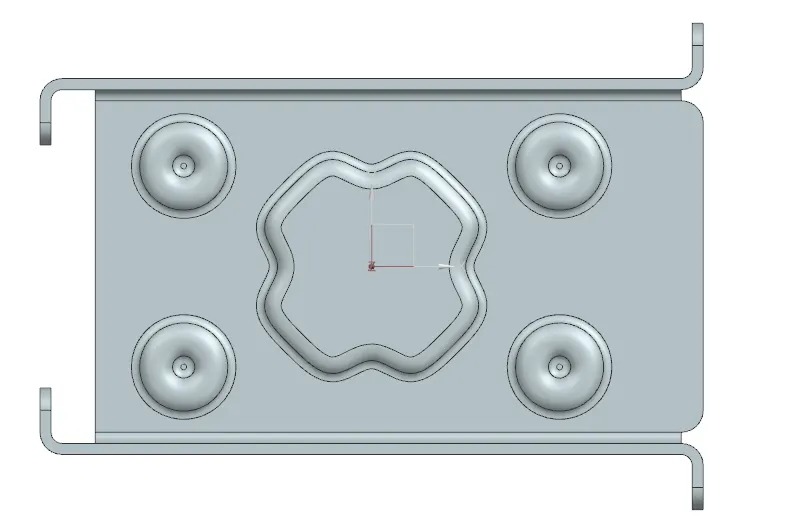
Top view
CONCLUSION:
Thus, using NXCAD we have designed CASING in sheetmetal module