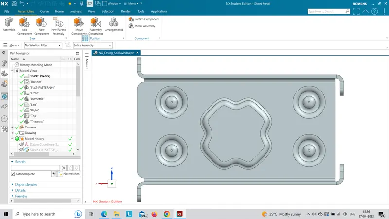
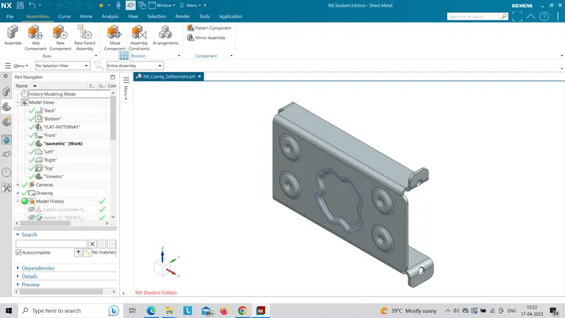
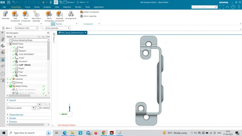
Advanced Sheet Metal Design Using NX Cad Challenge_1_Casing Design
Drafting
Title of the Project: Casing Design
Objective: Design casing in sheet metal workbench using nx cad.
INTRODUCTION
Casing may refer to an enclosing shell, tube or surrounding material. it may also refer as
- Casing borehole, metal tube used during the drilling of a well.
- Casing molding, decorative molding surrounding door or window openings
- Casing sausage, thin covering holding the food contents of sausage.
PROCESS
STEP 1 Open the sheet metal workbench, sketch 2d diagram draw the rectangle and use the tab feature with thickness of 3 mm.
STEP 2 Provide the flanges side to the tab and flanges can we provide and three tool but here i used simple fanlnge tool to by selecting bend ouside, and no relife.
STEP 3 Used the unbend and rebend operation to check whether the design following sheet metal shape or not, if not roll back to previews command check with option and dimension.
STEP 4 Provied the simple hole at the end of the flange and give the 5 mm diameter because the mating screw should to minimum tolerance within the hole and screw.
STEP 5 Provide the dimple feature, select the surface to sketch the circle of 8 mm, give the depth of the dimple and filp the direction along with depth directon.
STEP 6 Use the mirror feature to copy the dimple to the opposite direction.
CASING DESIGN
Sheet metal is formed by an industrial process into thin flat pieces. sheet metal is one of the fundamental forms used in metalworking and it can be cut and bent into varity of shapes.
COMMAND USED
1. TAB
Tab is only used in designing of sheet metal. Tab is base where the flange can be formed.
2. FLANGE
A flange is external or internal ridge or rim for strength as the flange of iron beam such as an I beam or T beam or for attachment to another object.
3. BREAK CORNER
Machining corner between two major elements of contour is called corner breaking. Breaking sharp corners between two element of a contour typically applies to 90 corner between a face and a diameter, or between diameter and face.
4. UNBEND AND REBEND
Use the unbend and rebend command to un bend and rebend non uniform thickness bends. In sheet metal non uniform thickness bends are created when you apply blends or chanfer, or counterbored holes, or tapered hole in the bend region. After the unbend or rebend non uniform thickness bends that are created across cylindrical or conical bends, closed corner feature. why should i use it? because non uniform thickness bends can also exist in sheet metal parts.
5. MIRROR FEATURE
Here we can mirror additional feature. These include curve feature, datum feature, and pattern feature created using the pattern feature command in the sheet metal application. NX creates a new sheet metal body when you mirror a base tab, a base contour flange or a dimple. you can mirror existing feature except for legacy instance arrays, legacy instance feature, legacy mirror features.
6. RESIZE BEND RADIUS
The fixed folded length type i now called fixed tab or flange position. When the change with the radius using this option, NX changes the geometry only in the vicinity of the resized bend, without changing the position of tab or flange.
In this command have some support for additional geometric condition.
1. zero bend radius
now create bends that have zero bend radii
2. Bend in partial flange
now modified the bend relief parameters using the option in the relief group.if you resize the bend in flange that have no relief NX create the relief when ever required.
3. Two adjacent bends
you can individully change the radius of the adjacent bends. if the change the radius of the adjacent bends. if you changesthe radius of one of the bends, the end caps of one bend or both bends are adjusted to keep the corner intact.if individully change the bend ra dius of adjacent bend that are not connected, but their bends caps are and do not form a corner. the bend radius.
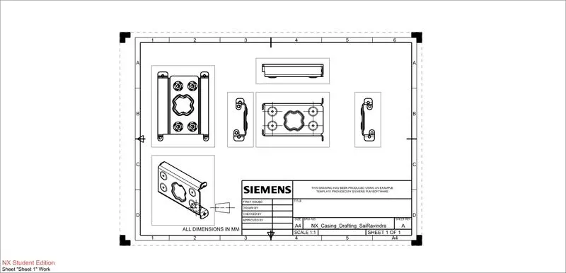
Drafting
Open the draft file in the nx and choose A4 sheet and click ok
and then add all the views of model and save it.