Week 8 - Challenge 5 - Core & Cavity Design
AIM: TO CREAT THE core and cavity DESIGN BY CREATING CLASS A B C SURFACES
OBJECTIVE: To creat a design a perform a draft analysis
INTRODUCTION :
CLASS A SURFACES - The surface which is givem to the pkastic modeler which is of aesthetic and outer most surface and the surface made by the designer known as clasa a surfaces
CLASS B SURFACES - The surfaces which is under the class A surfaces and which contain some engineering aspects on it is known as class B surfaces
CLASS C SURFACES - AT THE END the all classes of A B are going to be join called class c surfaces
FLOWING THE PROCEDURE STEPS:
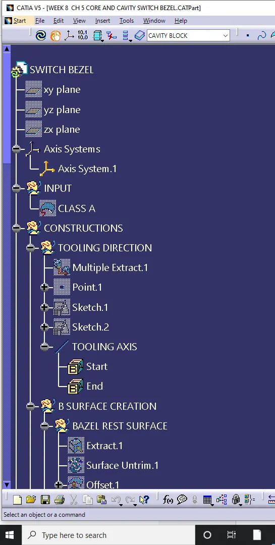
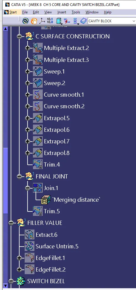
1) CREATING A TOOLING AXIS
2) PERFORMING DRAFT ANALYSIS
3) CREATING A CLASS A SURFACES
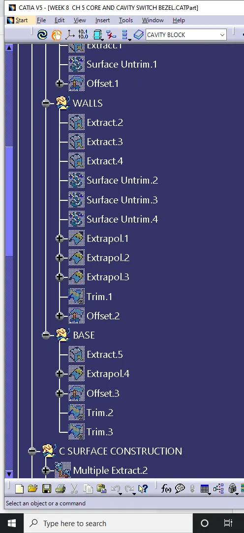
4) CREATING A CLASS B SURFACES
5) CREATING A SOLID MODEL
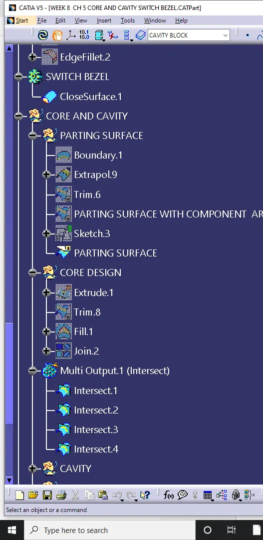
6)CREATING A CORE AND CAVITY DESIGN
7)CREAT PARTING SURAFCES AND PARTING LINE
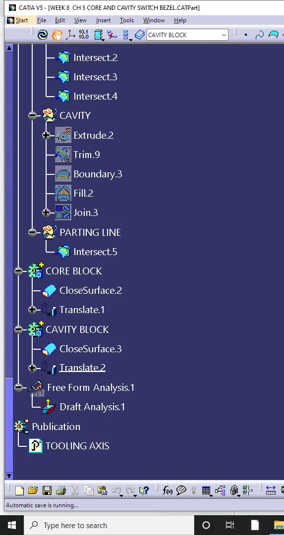
8)CREAT CORE BLOCK AND CAVITY BLOCK
HOW DO WE A CREAT A TOOLING AXIS ??
INITIALLY Obseve the class a surfaces before going to creat the tooling axis, and check wether it contain any discontinity and joined properly or not, have to check in all the x y z direction and we have to go with the top line and creat a axis called tooling axis
- Creat an intersection where we required, creat two lines at required intersectiojn and creat bijection line between them and also creat a dummy tooling axis
- extracting the suurfaces due to fillets and offset them upto 3mm\
PARTING SURAFCE
WHAT IS INJUCTION MOOULD PARTING SURAFCE ??
GENERALLY the injection mould has two majore components called as one is movable and another one is fixed halve and these 2 halves are pressed tightly and sealed hallows to avoid melting, this pressed surfaces are called parting surfaces
PARTING SURFACE DESIGN PRINCIPLE ?
Its directly effect the product quality and easy of construction
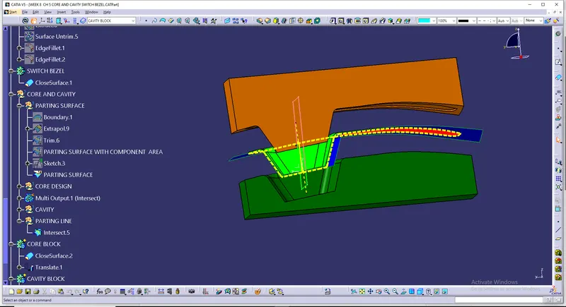
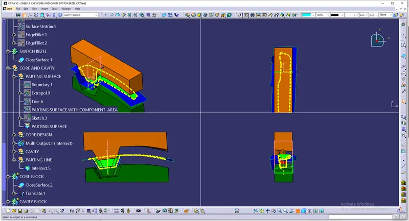
the final component will be shown as in
core, parting surafce, parting line, component,tooling axis and cavity