Advanced Sheet Metal Design Using NX Cad Challenge_1_Casing Design
OBJECTIVE
Design a Model of Casing using NX CAD.
INTRODUCTION
Casing made from Sheet Metals are used in a wide variety of applications.From home appliances to the aerospace industry, sheet metals are found everywhere. We need to follow few guidelines while designing structures and shapes using sheet metals. If you fail to follow these design principles, then there will be certain defects in the final products, which in results will not deliver the performance as per the requirements.
DESIGN METHODOLOGY
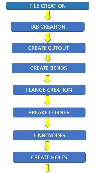
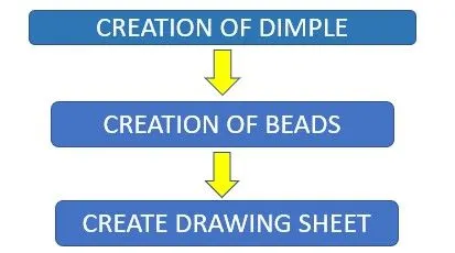
DESCRIPTION
FILE CREATION:- Create a sheet metal design file in Nx Cad and name it.
TAB CREATION:- Create a rectangular sketch on XY plane of 60mm length and 50mm width after that use TAB command to create a Tab of that sketch.
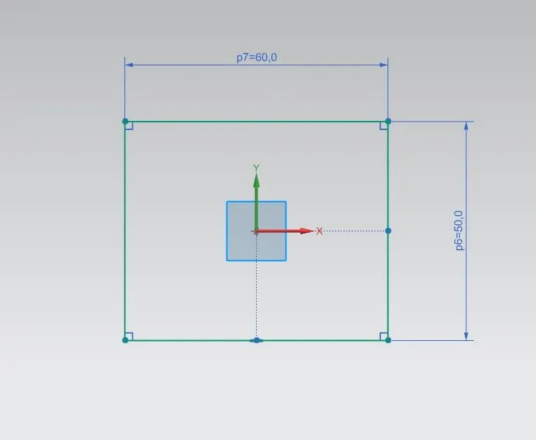
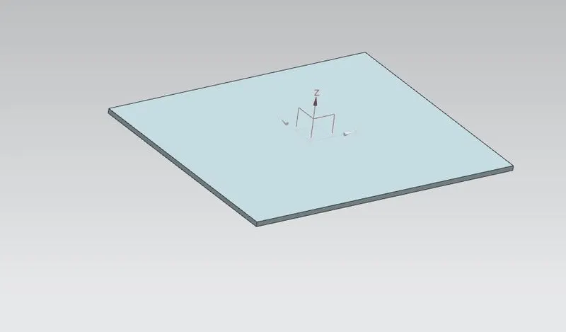
CUTOUT CREATION:- Create a rectangular sketch of 5mm wide and 40mm long which is coinside with the left side of the tab and use NORMAL CUTOUT command to make the cutout.

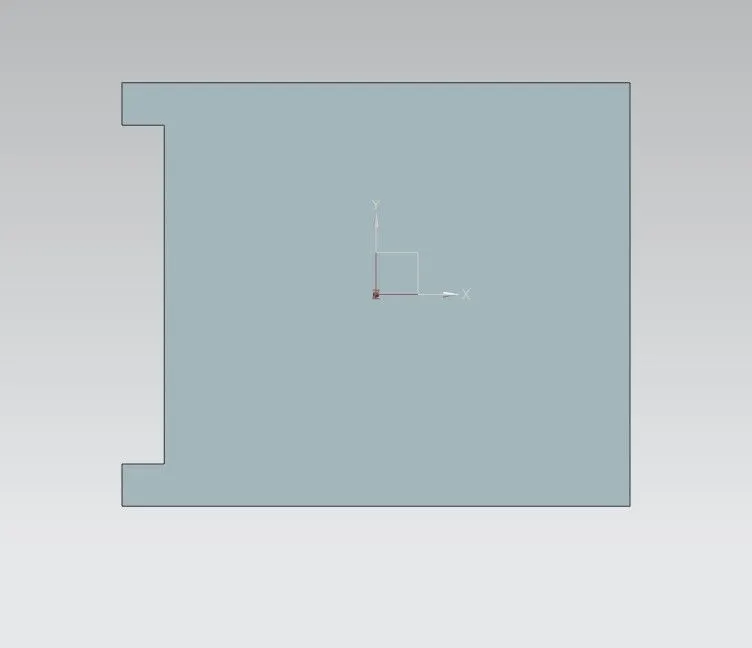
BEND CREATION:- Create two line of a distance of 10mm from the top and bottom and use BEND option to bend the Tab by using those lines. Bend should be 90deg.
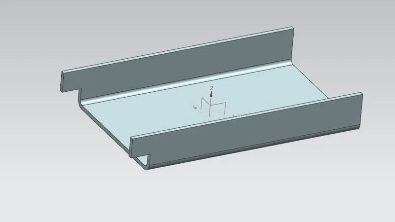
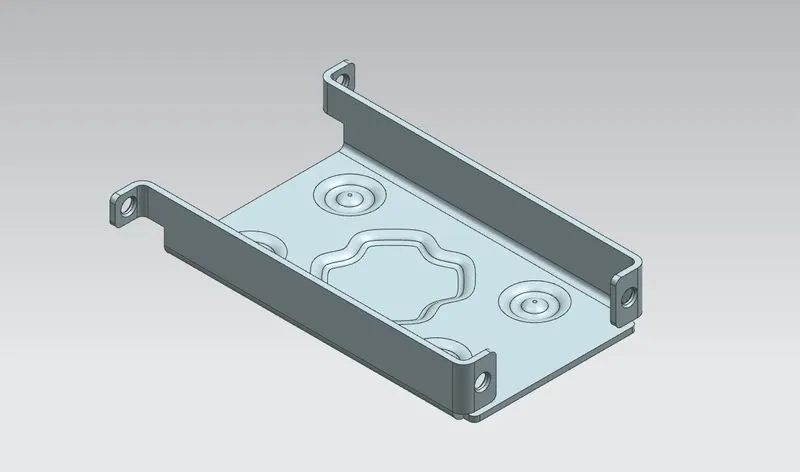
FLANGE CREATION:- Use FLANGES command to create flanges. The length of Flanges should be 5mm. After flange creation use BREAK CORNER command to smoothen the sharp egdes of flanges. The smoothen radius should be 1mm.
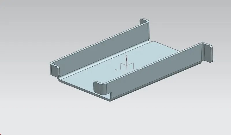
UNBENDING:- Use UNBEND command to unbend model. Select the faces and the bends.
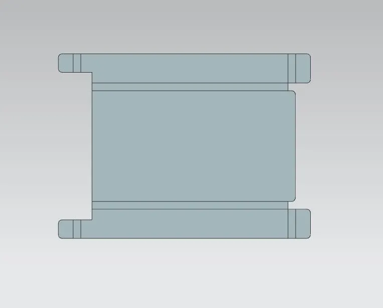
HOLE CREATION:- To Create hole on the flanges, first Create a point on the middle of the flange and use HOLE command to make the HOLES.
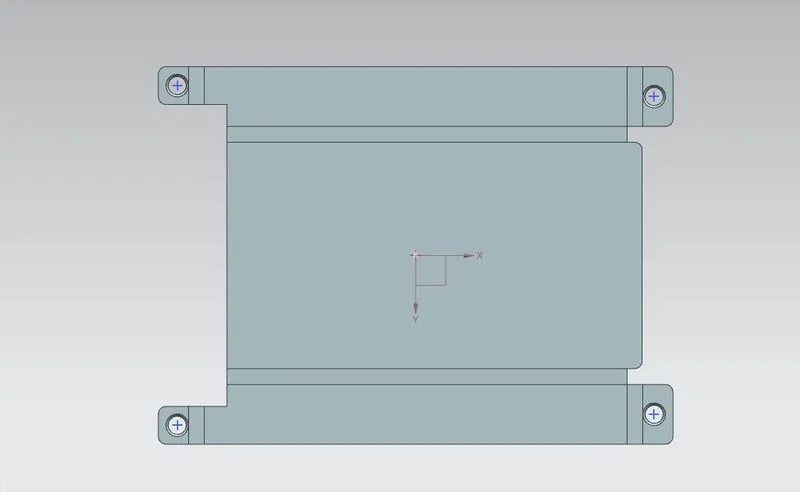
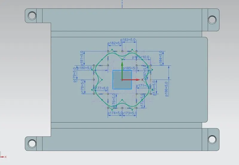
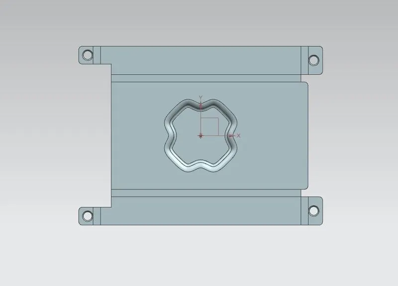
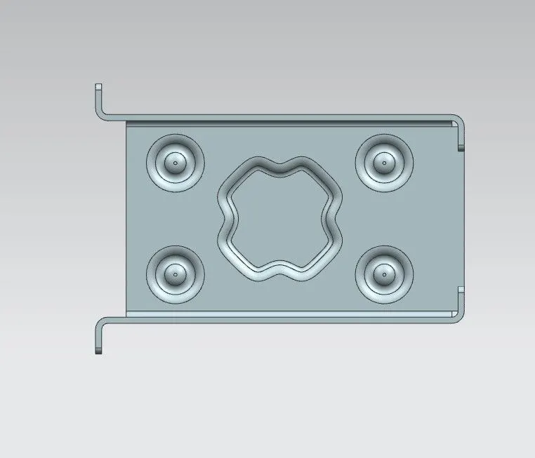
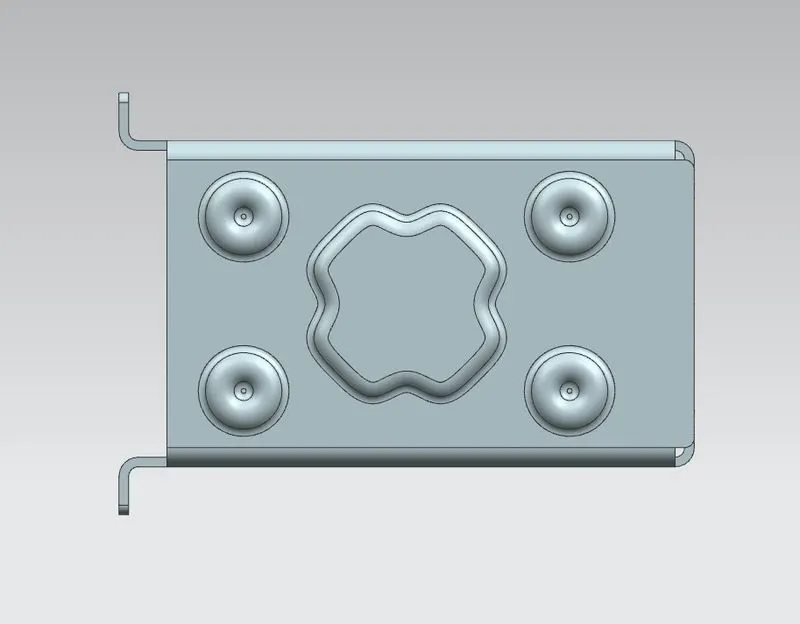
CREATION OF DIMPLE:- Create the sketch on the center of the part to make a dimple of that and Use DIMPLE command to create dimple. Dimple depth should be 1mm.
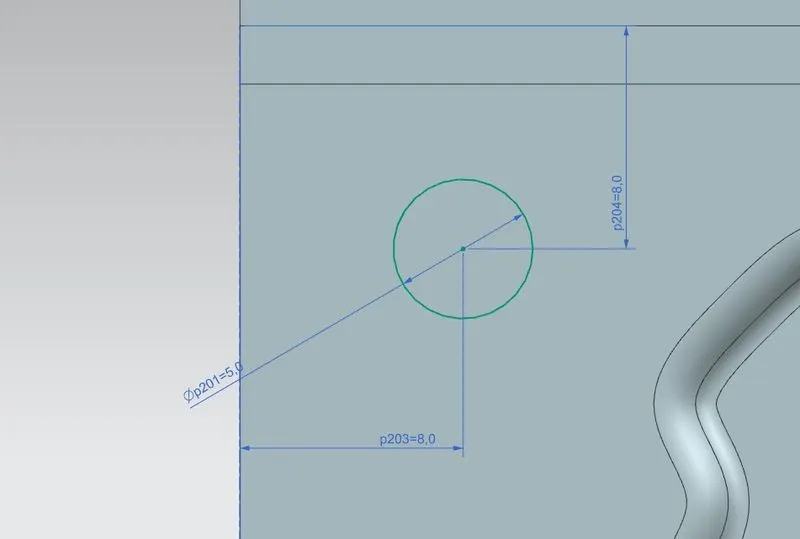
CREATION OF BEADS:- Create a circle of 5mm dia at the four corners of the part and Use BEAD command to create it.
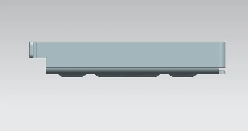
MODEL IMAGES
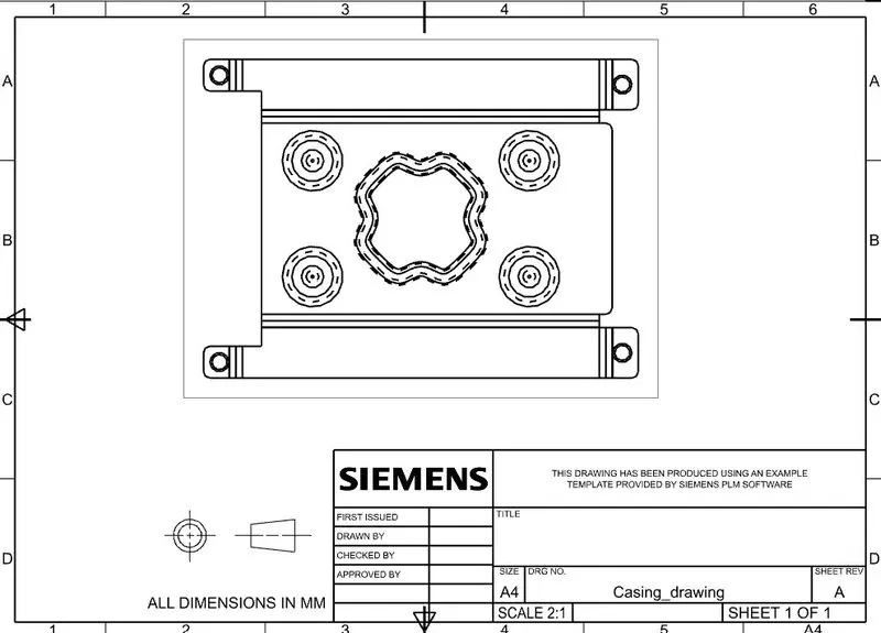
DRAWING SHEET IMAGE
CONCLUSION
This design of casing model is created using nx cad by following the design rules.