Advanced Sheet Metal Design Using NX Cad Challenge_1_Casing Design
SHEET METAL CASING DESIGN
Objective: To design an casing using the sheet metal application in siemens NX.
Introduction: Sheet metal is metal formed into thin, flat pieces, usually by an industrial process. Thicknesses can vary significantly; extremely thin sheet metal is considered foil or sheet, and pieces thicker than 6 mm (0.25 inch) are considered plate steel or “structural steel”. And sheet metal design is a vast domain in the design of any sheet metal industry,it is used many sectors including the aeronautics & automotive sectors, in this sheet metal casing design we will look at the design approch using NX (CAD) SOFTWARE through various design , images , explaination and images.
Types of Sheet Metal
- Aluminum
- Alloy steel
- Carbon steel
- Tool steel
- Galvanized steel
- Stainless steel
Applications
- Sheet metal is used in automobile and truck (lorry) bodies, airplane fuselages and wings, medical tables, roofs for buildings (architecture), and many other applications.
- Sheet metal of iron and other materials with high magnetic permeability, also known as laminated steel cores, has applications in transformers and electric machines.
- Historically, an important use of sheet metal was in plate armor worn by cavalry, and sheet metal continues to have many decorative uses, including in horse tack.
- Sheet metal workers are also known as “tin bashers” (or “tin knockers”), a name derived from the hammering of panel seams when installing tin roofs.
Design methodology (To be explained with the help of Flowcharts only)
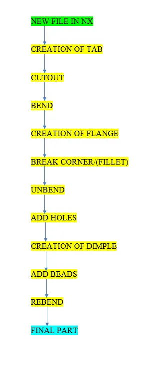
Description (Tools/ Features used while designing):
- Tab, a desired sketch was then created on to the base tab was created .later to that desired sketch was then created on the surface.
- Cut a section out from the tab using the nomal cutout option . required surface was bend to the to make perfect shape of casing.
- After sketching the line created and it should be bended to the angle of bend required.
- Flanges are added by 'flange command' to the corner for the gripment of privously bended surface.
- Break corner option are usefull so that it make us to view neatly and smoothly it help to radius the sharp corner.
- Unbend is done through unbend option will make the bended sheet metal to unflap to the size and shape of sheet to manageable requirement .
- And the sketch is added to the surface to make the holes on it using hole option.
- Dimple firstly we need to sketch on to the surface a shape using studio spline and later on the depth is added , the sketch has to be rotated to desired angle.
- Bead was added using bead dialogue box , the bead was then mirrored multiple times using the mirror feature option after having desired design the model was unbended using the command.
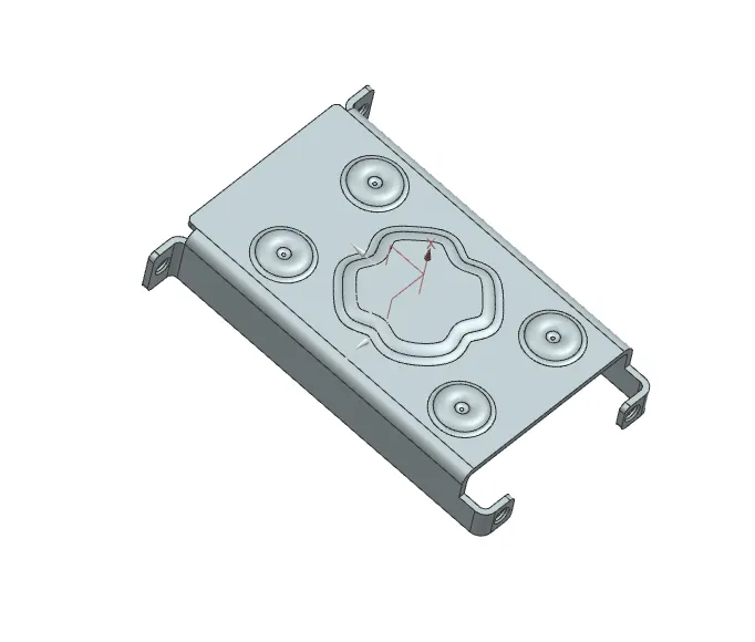
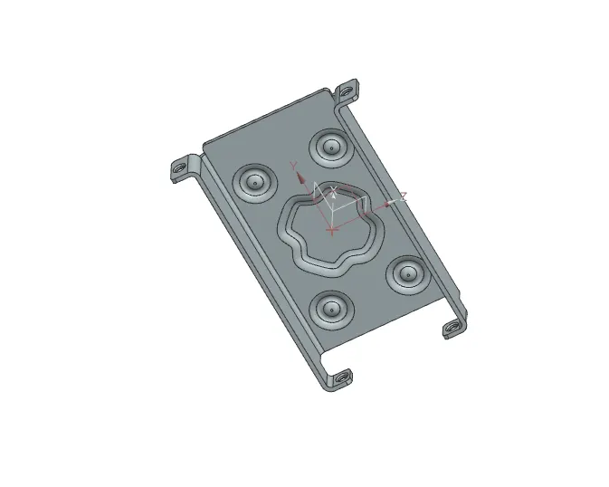
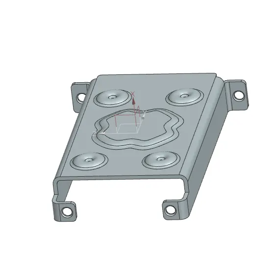
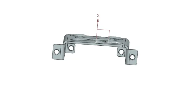
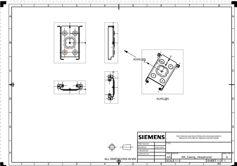
Screenshots of (Front View, Side View, Isometric View and the Top View)
Detailed Drawing Sheet Image
Conclusion : Finallly By using sheetmetal commands and given data created the sheetmetal casing.