Advanced Sheet Metal Design Using NX Cad Challenge_1_Casing Design
Casing Design
Objective:
Write a detailed report on Sheet Metal Component with good explanation on Sheet Metal modelling tools applied throughout the modelling
Introduction:
Design Methodology :
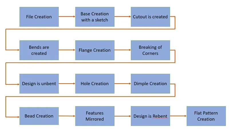
Description:
The commands used for the creation of this design is as stated below:
1. Tab: Tab is a command used only in sheet metal designing. The tab command allows for a base to be formed with the help of a base sketch.
2. Normal Cutout: This command helps in cutting the sheet normal to the surface.
3. Bend: The bend command helps with providing a bend on the material on one side of the sketched bend line.
4. Flange: The Flange command is used to create flanges on the edge of the material. It is used for to either strenghten then material or to provide a mating surface to another component
5. Break Corner: This command is used in sheet metal design to remove sharp edges and provide smooth surfaces at those edges.
6. Unbend: This command is used to remove all the bends in the design and create an open flat and flat design so that other features can be created on mulitple faces for example.
7. Rebend: The rebend command works in the exact opposite way to the unbend command. Once unbent and worked upon, and once the sheet metal is ready to be bent back to its initial design, the rebend command is used. The unbend and rebend command is used in tandem, that is, if the unbend is command is used then the rebend command will follow.
8. Hole: This is a command that is used in both sheet metal and the modelling application. It is simply used for the creation of holes on the surface.
9. Dimple: The dimple command is used to create indentation of our design on the suirface of the sheet metal.
10. Bead: It is used to create elongated recesses which are stamped into the sheet metal parts to increase the stiffness on the sheet metal.
11. Mirror Feature: This commadn is used to mirror a certain feature in the design about a central plane of choice.
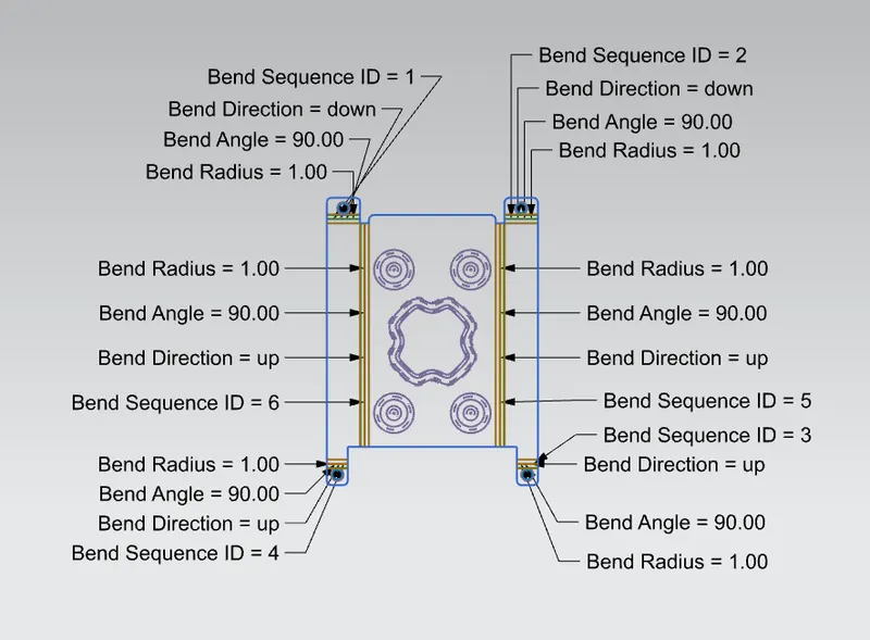
12. Flat Pattern: This command is once the design has been finalised to provide a flat 2D drawing of the intended design.
The various perspective views of the final model is provided below :
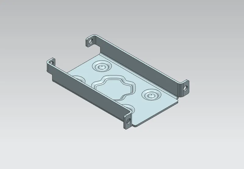 Isometric View
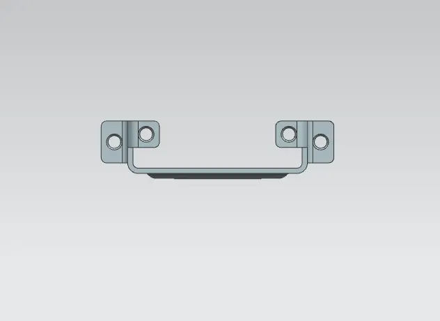
Side View
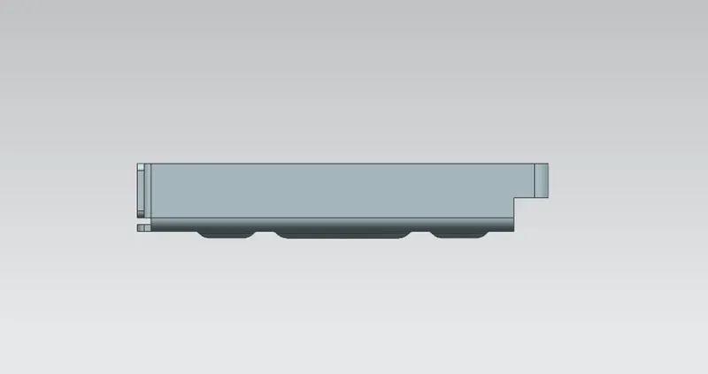
Front View
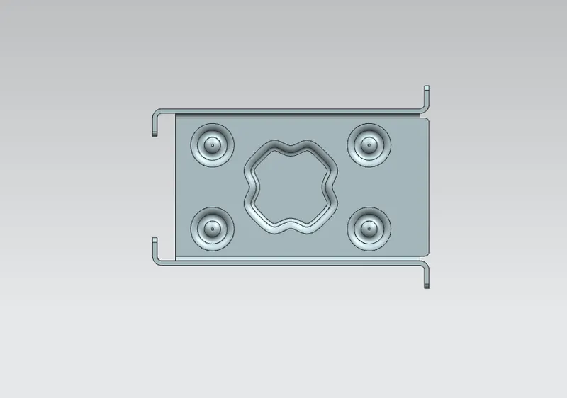
Top View
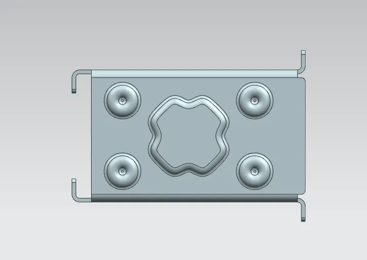
Bottom View
Conclusion:
Hence the design was created from the given requirements and was optimised for manufacturability.