Advanced Sheet Metal Design Using NX Cad Challenge_1_Casing Design
AIM-DESIGN OF AUTOMOTIVE SHEET METAL CASING & DRAFTING
OBJECTIVE-USING THE SHEET METAL COMMANDS LIKE TAB,BRAKE CORNER,FLANE ,DIMPLE DESIGNING THE COMPONENT IN THE DESIRED SHAPE.WITH FOLLOWING THE DIMENSIONS.
INTRODUCTION
Sheet Metal is a type of material that is flattened into thin sheets. Sheet metal is made by taking a large cast in and rolling it into a long ribbon of the thickness it wants. This flat metal is rolled into a coil and sent directly or cut the metal into sheets before being sent to a machine shop.
The most common sheet meta; used in automotive to make bodies is mild steel.it ia reasonabily cheap & easy to press in to desired shape. the next is aluminium it is lighter in weight but much harder to bend in to tight shapes without cracking.it is also hard to weld in mass production.
to design the sheet metal parts different industries uses various softwares like catia v5, siemens nx cad,solidworks,etc.
i am using SIEMENS NX CAD SOFTWARE to design this casing in this challange.
DESIGN METHODOLOGY
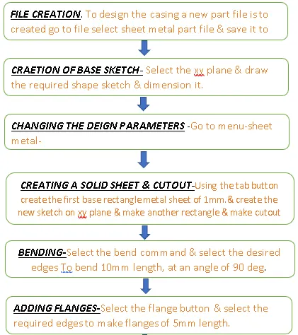
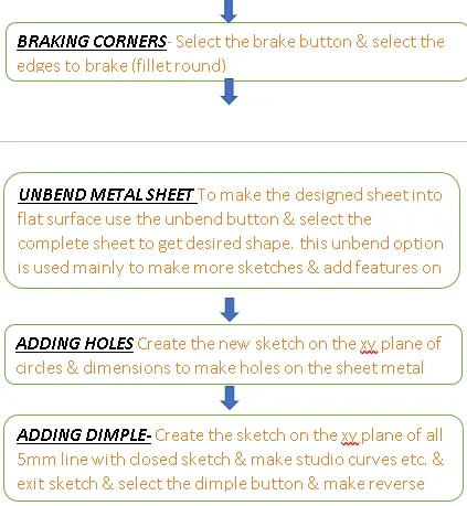
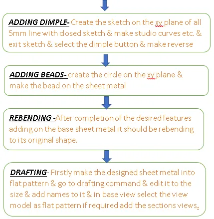
TOOLS USED TO DESIGN THE SHEET METAL CASING.
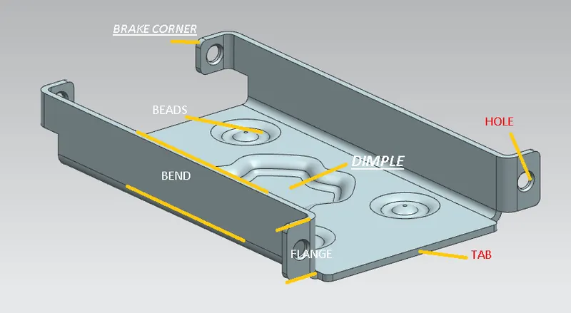
- SKETCH thsi sketch is used to create the basic sketch of the design to start on selecting the desired plane i.e, on XY plane ,& draw the line on that plane & in the similar way the sketch is used where ever it is required.
- TAB- this feature is used to make the base surface with the drawnsketch selecting the curve with the thickness of 1mm.
- CUTOUT-create the sketch on xy plane & draw the rectangle of 5mm in x direction & 40 mm in y directionmake origin as mid point of the rectangle.& coincide the left edge of the recangle to the left edge of the base sheet metal.
- BEND-this feature is used to make the bend the sheet metal of 10mm length by selectimng the desired edges to be bend.
- FLANGES-This feature is used to add the flanges to the edges of the sheet metal. two edges out sie & other two edges inside.by selecting the edges by default nx will create the releafs so that it willnot effect the sheet while manufacturing.
- BRAKE CORNERS-Breake corners feature is used to make the sharp edges rounded by cutting the unwanted materail by default. bend is nothing but (FILLET)
- UNBEND- Unbend feature is used to make the shhet metal shape part in to flat to analyse the part is perfectly aligned with the features & a;lso to add the required features lke holes,dimples,beads etc,
- HOLE,DIMPLE,BEADS- These all comes under the punch commands added on the sheet metal to strengthen the metal.
- MIRROR-This feature is used to reflect the designed featue same at the other face by selecting the plane or the centreline instead of remake the same sketch or feature. & the main use of the mirror features is it reduces the modeling time.
- REBEND- This feature is used to make the bend sheet metal into the requred shape after adding all the desired feature on the sheet to regain its original shape.
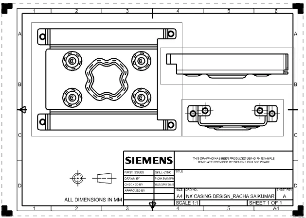
- DRAFTING- This feature is used to make th drawing of the designed sheet metal part into a drawing sheeet representing the pre model of how the model to be like 2d sketch on a paper model.it consists of dimensions sctional views like isometric,front,side,etc.
CASING DESIGN ISOMETRIC VIEW
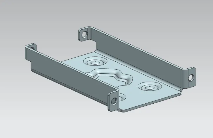
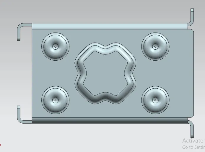
TOP VIEW
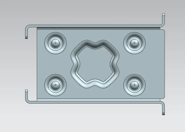
UNBEND VIEW
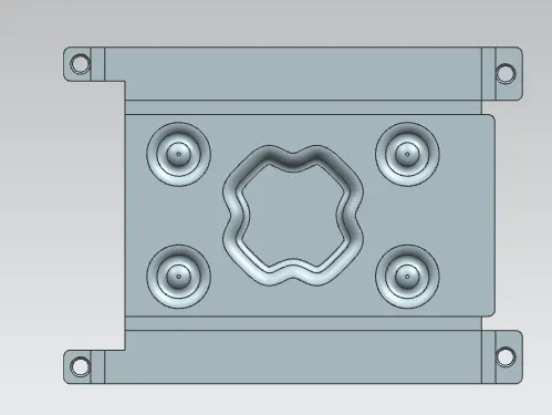
FRONT VIEW
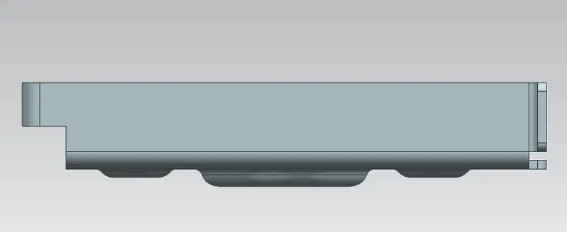
RIGHT SIDE VIEW
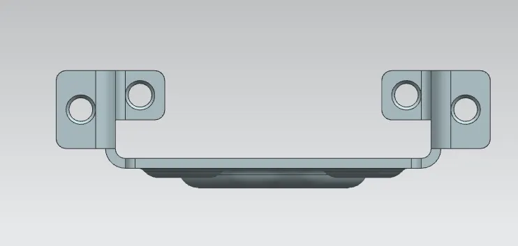
BOTTOM VIEW
DRAWING SHEET(drafting)
CONSLUSION DESIGN OF SHEET METAL CASING & DRAFTING IS DONE & DETAIL EXPLANATION OF THE USED FEATURE TO DESIGN THE SHEET METAL CASING IS DONE & RELATED IMAGES & FILES ARE ATTACHED IN THE ANSWER BOX.