Advanced Sheet Metal Design Using NX Cad Challenge_1_Casing Design
Designing Sheetmetal Casing
Objective : To design Sheetmetal casing using NX CAD software in sheetmetal work bench.
Introduction :
Sheet Metal is a type of material that is flattened into thin sheets. Sheet metal is made by taking a large cast in and rolling it into a long ribbon of the thickness it wants. This flat metal is rolled into a coil and sent directly or cut the metal into sheets before being sent to a machine shop.
The sheets are made from different kinds of metals such as aluminum, brass, copper, steel, tin, nickel and titanium. The sheet’s thickness depends on the material needed for a project. Thicknesses can vary from 0.15 -6.00 mm significantly; extremely thin sheets are considered foil or leaf, and pieces thicker than 6 mm (0.25 in) are considered plate steel or “structural steel.”
Designing the products with the sheet metal comes with its limitations but has many benefits that can work with this design material that outweighs cons. It is available with numerous coating for corrosion resistance or surface finish.
Sheet Metal can be useful for large and durable parts with few features. They make good RF shields, ground planes and thicker gauge parts for adding strength and weight to the things. Sheet metal is not suitable for minimal parts, complex or precise geometry, cosmetic parts or lightweight parts.
Most of the metal fabrication businesses rely on 2D drawings even though the 3D model is available in the market. At the manufacturing floor, drawings are utilized to develop production plans. The purchasing department uses it for technical packages while other departments like quality and marketing utilize drawings to develop different publications. So this is where Sheet Metal Drafting comes into role.
3D Drawings are still prevalent and affect productivity to a greater level of significance. 2D drafts are challenging to manage and prone to errors that cause miscommunication and production wastage. Though these is known by fabricator but somehow stuck with 2D processes either by losing business while transitioning or due to resistance from experienced internal resources. 3D CAD Model opens up the multiple opportunities for sheet metal fabricating businesses to remain competitive, productive and profitable.
Sheet metal is one of the versatile materials in the manufacturing and construction industry with applications in every industry from mining, construction, farming, catering, hospitality, shipping, manufacturing, aviation, medical and transport.
Design Methodology
After opening the softwafre steps that is perfomed for creating sheetmetal casing.
- Select a new file in NX CAD
- Saved with suitable name
- Select the XY plane to draw the sketch
- Tab is created with reference sketch
- Advanced flanges on the edges of the bends create in previous step
- Bending operation done on side of the tab behind the cutout
- on the tab created as sketch to perform normal cutout operation
- Unbend the sheetmetal by using unbend command
- Add the holes where ever required by using hole command
- Skectch is created on surface of the tab to perform dimple operation
- Studio spline option is selected to create spline curve
- Rebend the sheetmetal by using rebend command
- Rotate spline curve to 45 degrees
- Final product is ready as per input provided.
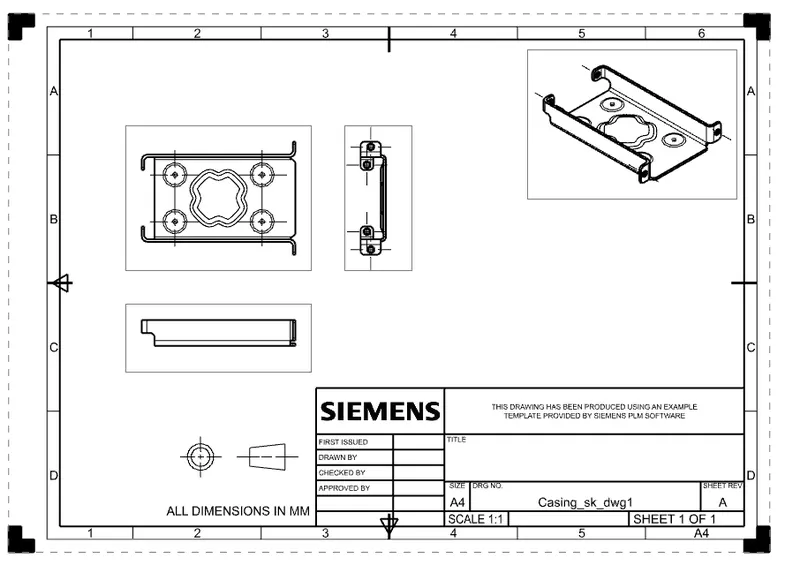
- Drawing has been created with 2:1 scale
Images of the CAD Model :
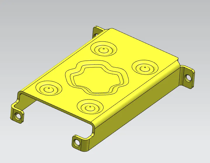
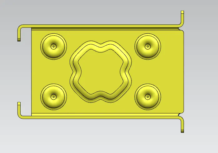
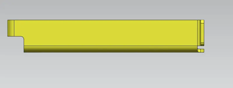
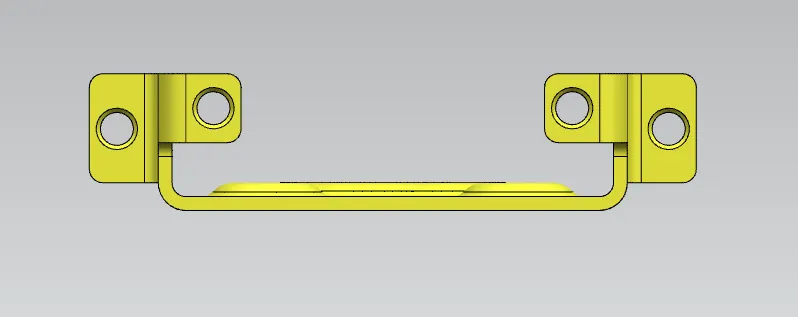
Drawing of Casing:
Conclusion:
The casing model helped in usnderstanding various sheetmetal operation in NX and how to perform them.
Gives a good Tool environment knowledge in NX sheetmetal workbench.
Casing Part is attached.