Advanced Sheet Metal Design Using NX Cad Challenge_1_Casing Design
MODELLING OF CASING
OBJECTIVE: The aim of this project to model a casing following the dimension guidelines ,it has to be done using NX sheet metal application.
INTRODUCTION: Casing is the one which is used to cover an object or thing,which is nothing but an enclosing frame.The casing is designed and manufactured using sheet metal in the NX software.In automobiles the batteries can be guarded in casing.
FEATURES USED:
tab: The tab feature is used to thicken the defined sketch which is rectangle in the casing.
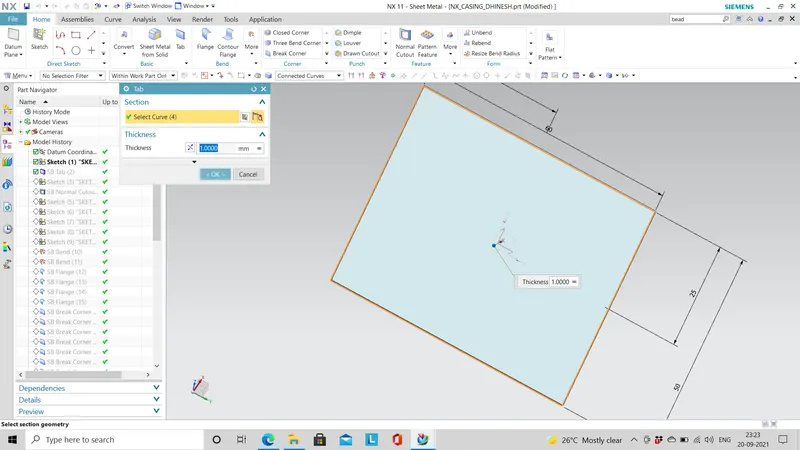
normal cutout: The cutout option is used to remove a part which is sketched
bend: It modifies the casing flat model by bending with respect to the sketch we created.
flanges:The flanges are used to bend the edge of the model with angle and length dimensions,it can be on any side as per our choosing of edge.
break corner:This is used to smoothen the sharp corners by chamfering with blend radius value.
unbend: It is used to unbend the bended parts by choosing a bend radius curve.
hole: Using this command a hole can be created with some center point and the hole radius value should be provided.
studio spline: The studio spline is used to create and edit spline by dragging points or poles and assigning curvature at the defined points
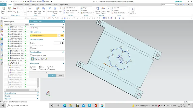
move curve: The move curve point is used to move the whole curve with some axis point at some distance and some distance.
dimple:This dimple is used to bulge a particular area within the sketch boundary.
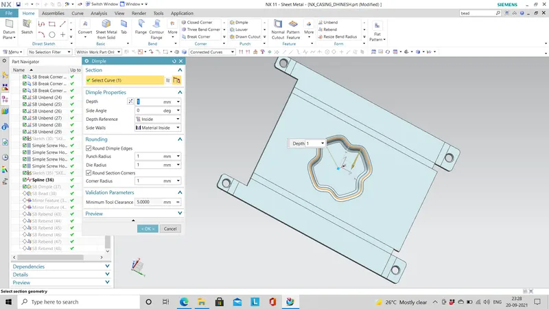
bead:This bead command is used to lift a particular area within the sketch boundary with die radius.
rebend:The rebend command is used to undo the actions of unbend and get the original shape
ORIENTATIONS OF MODEL:
TOP VIEW:
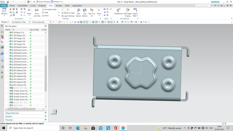
BOTTOM VIEW:
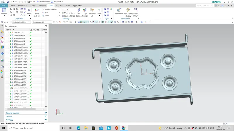
FRONT VIEW:
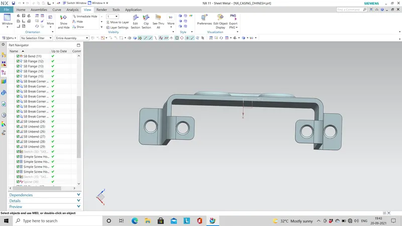
SIDE VIEW(LEFT):
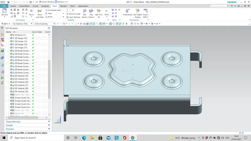
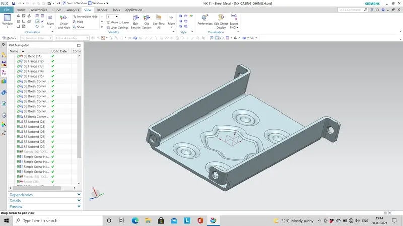
ISOMETRIC VIEW:
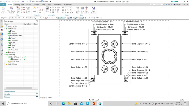
DRAWING SHEET IMAGE:
After drafting the model would like below image with base view as flat pattern .
CONCLUSION:
The design of casing in sheet metal using NX is modelled successfully and the various orientation of the model also captured.
Drafting of the same model with the flat pattern is also achieved successfully. The model part and drawing part is attached