Advanced Sheet Metal Design Using NX Cad Challenge_1_Casing Design
Casing Design
Objective:
The main objective of this project is to design a sheet metal casing in NX cad sheet metal application workbench. Also to perform the drafting for the casing part.
Introduction:
The sheetmetal application provides an environment for the design of sheet metal parts used in Machinery, Automotive and Aerospace. Enclosures, Brackets and other parts are normally manufactured with break press. The sheet metal application are widely used in the:
- Aircraft Bodies
- Automobiles
- Utensils used for domestic purpose
- Beverage cans
In sheetmatal application we can create a uniform thickeness sheetmetal parts using basic features such as flange, tabs and jogs. We can also do close corners, cutout and stiffening features. The complex sheet metal part can be desinged in the solid model workbench and then we can convert it into a sheet metal part. We can also import, clean up and convert a non sheet metal part into a valid sheet metal part. Flat pattern sheet metal data can be used for the manufacturing process. The Material parameters such as thickness, bend radii and bend relief can be easliy set as default settings.
Design Methodology:
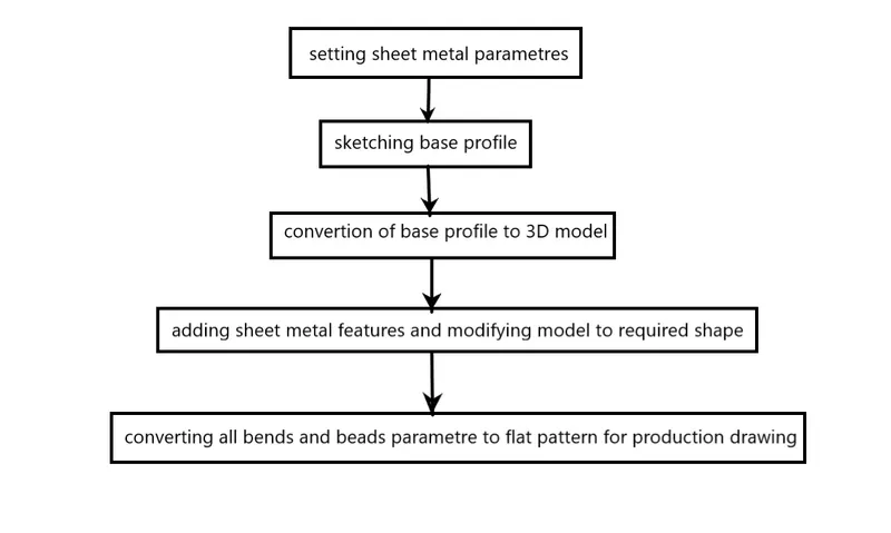
Description:
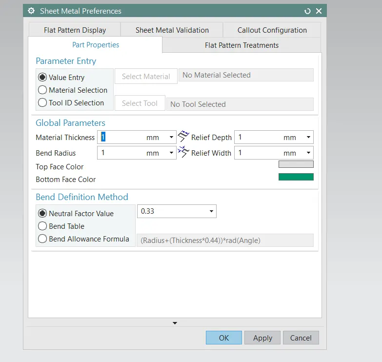
Setting Parameter:
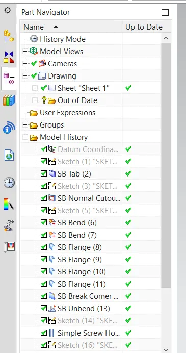
In this section basic sheet metal parameter are set to obtain uniformity in design as per the material selection. Here all parameter are set 1mm sheet metal.
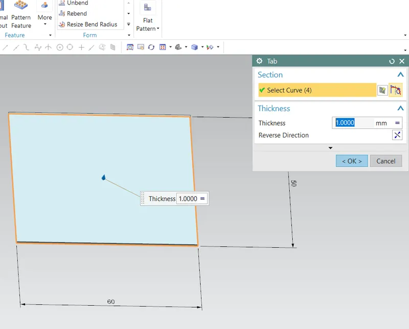
Tab Feature:
It is similar feature to the extrude function but the extrude value limit to the global value set in parameters and can be edited local settings. Base sketch is required to execute this function.
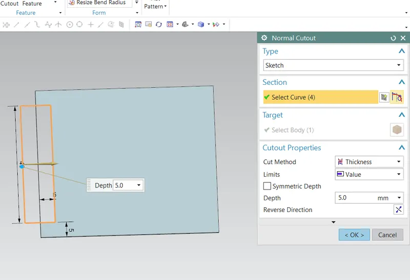
Normal cut-out:
This feature help to cut or remove undesired profile from the base model.
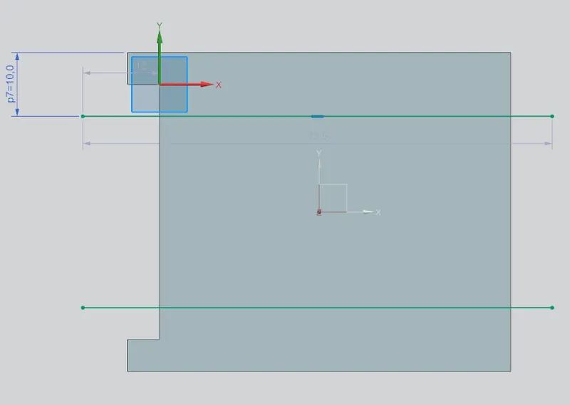
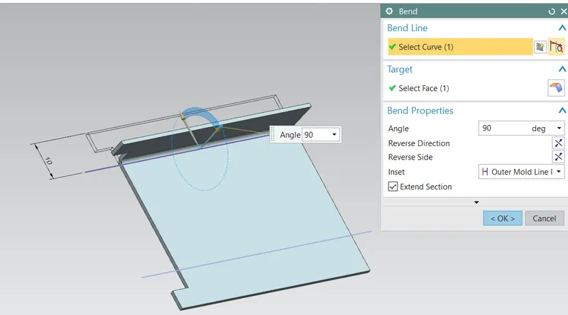
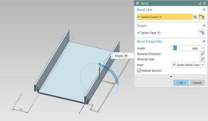
Bend:
This feature help to bend the sheet from the particular edge with reference to the bending line to different angle measuring from the fixed surface. Bending radius are taken automatically as defined in global setting.
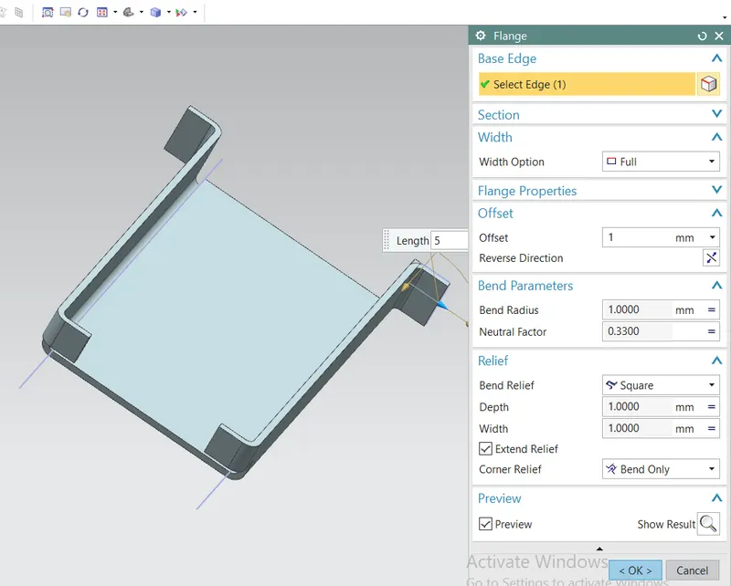
Flange:
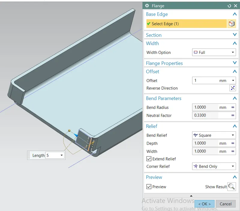
This feature used to add a flat flange at angle to planar face . Different type of flanges type are available in option to control the profile of flange. It require edge to finish command.
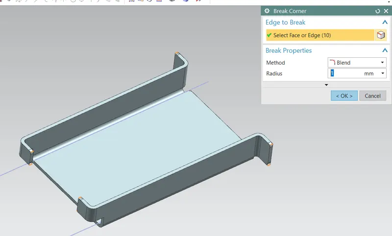
Break Corner:
This feature help to smooth out the sharp edges on the corner by rounding the edge or creating chamfer shape.
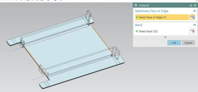
Unbend:
This feature help to unbend all flanges and bended area into flat surface. This function help to create extra feature on the bend surface like holes emboss etc which are applied to normal to flat surface. also help to visualise to before and after shape of bended sheet.
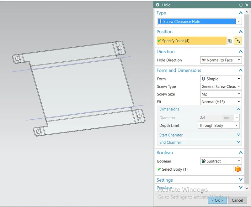
Hole feature:
To create hole feature with screw parameter, points has to be defined on the unbended surface and in hole parameter desired specification to be selected in order to create the pattern. Here M2 screwed holes are selected.
Dimple:
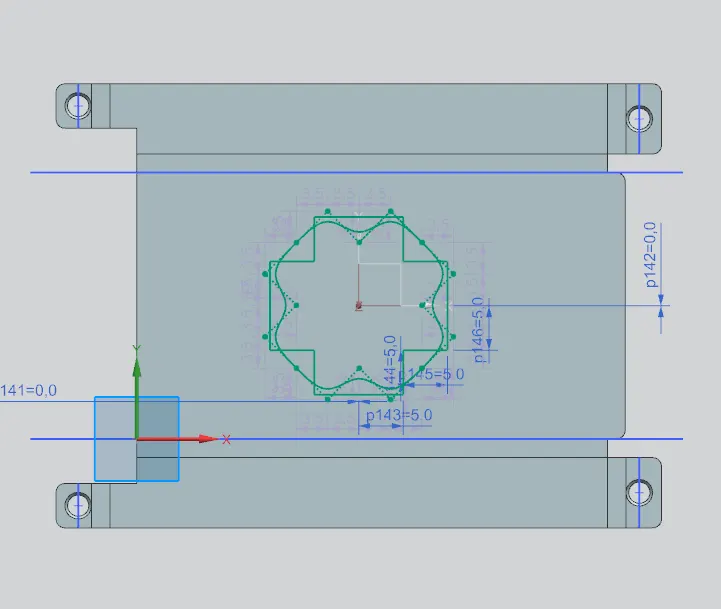
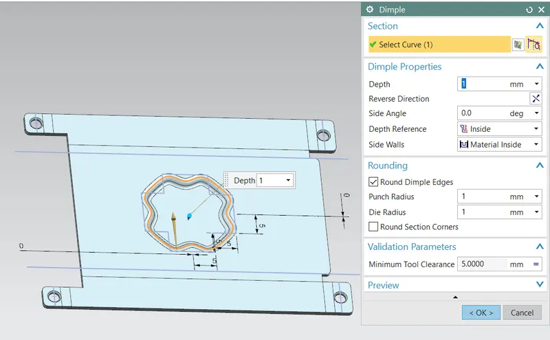
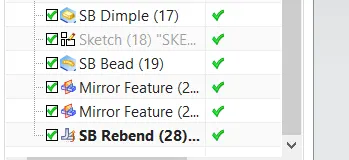
This command create emboss feature inside the sketch that stimulate a stamping tool. It provide over the length to increase the local strength and rigidity of the cross section and structure.
Beads:
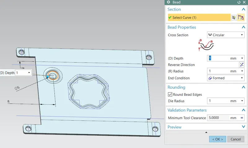
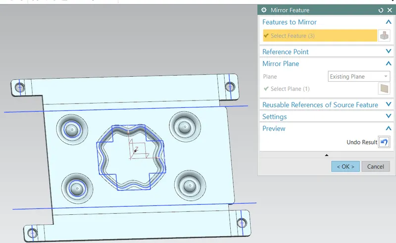
This feature lifts the material along the counter of sketch that stimulates stamping tool. It also adds strength and rigidity into structure.
Rebend:
It is undo the unbending command with all the features added to the flanges and associated surface and resemble final shape of the sheet metal.
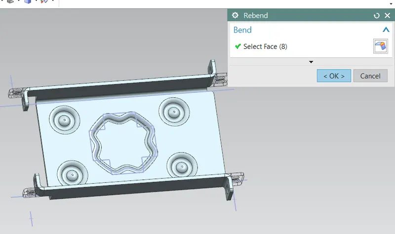
Front View:
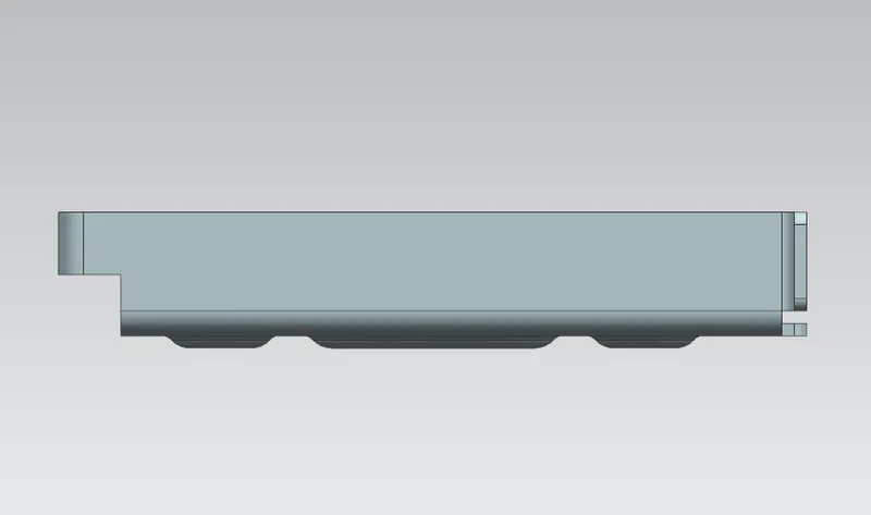
Side view:
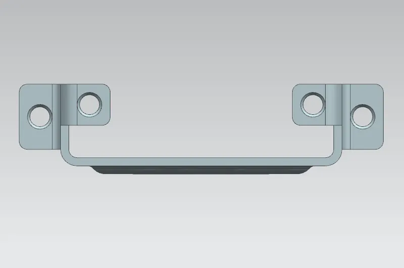
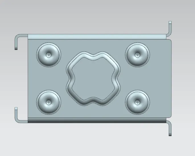
Top view:
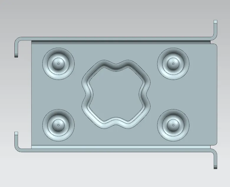
Bottom view:
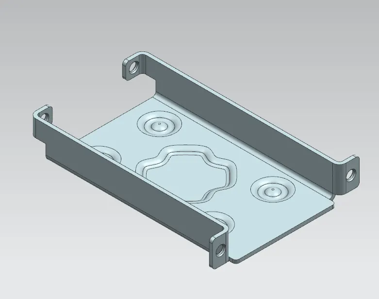
Isometric view:
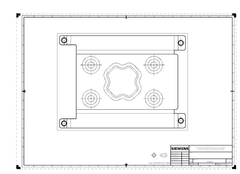
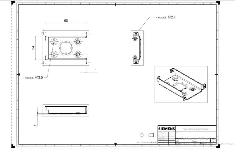
Drafting:
Conclusion:
Casing design is completed using sheet metal workbench in NX cad applying the sheet metal parameter considering the manufacturing parameters as provided in input data.