Advanced Sheet Metal Design Using NX Cad Challenge_1_Casing Design
Casing Design
Objective:-
To design a Sheet Metal casing design using Siemens NX Sheet metal application.
Introduction:-
- SIEMENS NX:- NX formerly known as "unigraphics", is an advanced high-end CAD/CAM/CAE, which has been owned since 2007 by Siemens PLM Software.
- SHEET METAL DESIGN:- NX Sheet Metal Design provides the design professional with a complete set of tools to efficiently create and manage sheet metal parts based on the knowledge of material properties and manufacturing processes. NX Sheet Metal Design tools incorporate material and bending information, enabling the model to represent both the formed component and flattened blank shapes
DESIGN METHODOLOGY
TOOLS USED
1.SKETCH :-
A Sketch is a named set of 2D curves and points located on a specified plane or path.You can apply rules, in the form of geometric and dimensional constraints, to establish the criteria your design needs.Features created from a sketch are associated with it, if the sketch changes so do the features
2.TAB :-
create a base feature by extruding a sketch along a vector by a thickness value, or by adding material to existing faces and bend regions of a sheet metal part
3.FLANGE:-
Flange command use to add a flat flange at an angle to a planar face and adds a blend between the two
1.Click flange command icon.
2. In the graphics window, select the edge to add a flat flange.
3. In the flange properties group.
- Select full option in the width option list.
- Set the length value in the length box. Click to change the direction if you want. In the length reference box, you can select more option as: inside, outside web, tangent.
- Select the angle of flat flange.
- In the inset box, you can select the method to inset material as: material inside, material outside, bend outside, material inside OML.
- Select the offset you want.
4. Click OK to finish this command.
Note: If you want to use a different bend radius value, you need to draw arcs in the section, or change the default bend radius value.
4.UNBEND:-
This feature is used to unbent the sheet metal taking any one face as a stationary face.
Flattens sheet model through selected bends.
To activate command:
- Click on command on (When sheet metal application activated.) “ Home => Form down arrow => Unbend”
- Activate command from “Menu => Insert => Form=> Unbend”
For Using “Unbend” command:
- Activate the “Unbend” command.
- Select the stationary face of the sheet metal.
- Select edges to bend
5.REBEND:- Rebends, the unbent feature of the sheet metal model.
It uses after the “Unbend” command If needed.
To activate command:
- Click command on (When sheet metal application activated.) “ Home => Form Gallery => Rebend”
- Activate command from “Menu => Insert => Form=> Rebend
- Select unbent faces on the model. (“Select Face” in the “Bend” tab highlighted automatically when command activated.)
- If you want to define stationary face on sheet metal model, click down arrow in the command window to open more options. Click on “Select Face or Edge“ in the “Stationery Face or Edge” tab in the command window. The function will be highlighted. Select stationary face on the model.
- Click the “Ok” to finish
6.DIMPLE:- The Dimple command to lift an area of the model inside a sketch that simulates a stamping tool. A Dimple feature across cylindrical bends in the unbent state. An open or closed section type of the Dimple feature can be created across a bend and a planar face, or completely inside the bend
7.BEAD:- Used for giving strength to the sheet metals
Bead command to lift material along the contour of a sketch that simulates a stamping tool. Beads can also be created to stiffen sheet metal parts.
- Choose Weld Assistant tab→Sealer group→Bead.
The Bead dialog box opens.
- In the Type group, Ellipse is selected.
- In the Primary Parts group, Select Face is active.
- Select a face on the primary part.
- In the Secondary Parts group, click Select Face and in the graphics window, select a face on the secondary part.
- In the Path group, click Select Curve or Point and in the graphics window select the curve you want to sweep the cross section along.
- In the Parameters group, set the parameters for defining the cross section.
- Click OK to create the Beadfeature
DESCRIPTION
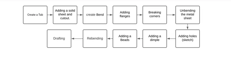
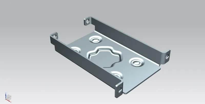
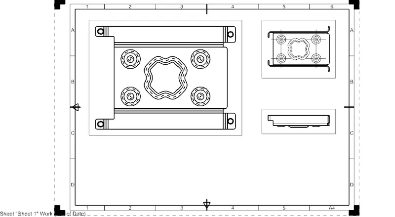
- Start NX 11 and create a new Sheet Metal. Create a sketch in the XY plane and draw a rectangle centred at the origin with an x-length of 60mm and a y-width of 50 mm.
- Use the Tab button for creating a first rectangular metal sheet of 1 mm in thickness.Create a new sketch in the plane P containing the upper face of the rectangular sheet and parallel to the XY-plane. In that sketch, draw a rectangle symmetric ta w.r.t the x-axis which is coincident with the left edge of the rectangular metal sheet. The rectangle is 5 mm wide and 40 mm long. Exit the sketch mode and use the Cutout button Normal *Plane - P Cutout for making a rectangular hole in the TOP metal sheet.
- click the Bend button, under the More button of the Bend field. select one line as Bend Line and use an angle of 90 degrees. Redo the same procedure for the other
symmetric, line. - Click on the Flange button . Use a Length of 5mm and apply the flange on the shown edge of the metal sheet. Apply the same flange to the corresponding symmetric edge of the sheet metal
-
Click on Break Cornerdialog box, use the Blend method with a Radius of 1 mm.Apply the Break Corner to the edges
-
Click on the Unbend button & Unbend In the Unbend dialog box, select as Stationary Face the larger horizontal (inside the plane P) face of the metalsheet. Select as Bend face one of its adjacent face.
- Adding holes, Click on the Hole button under More button of the Feature field. In the Hole dialog box, use Screw Clearance Hole as Type, with a M2 Screw Size and a H13 Fit. Set the Depth Limit option to Through Body. Create four holes centred on the four previously defined points.
- Adding dimple, In the XY-plane, create the following cross sketch, where each (half-) side is 5 mm in length. The sketch is centred at the origin (0,0,0). Click on the Studio Spline button In the Studio Spline dialog box, set the Type field to By Poles. Check the Closed option.Select one by one all the 16 points of thesketch in a clockwise (or anticlockwise) fashion. Click OK to validate the creation of thenew spline curve.
- Click on the Dimple and select the spline curve. Set the Depth option to 1 mm and Side dimple Walls to Material Inside. Expand the dialog box and expand the Rounding field Side Angle 0 deg by left-clicking on it.Set all the parameters of the Rounding a field to 1 mm. Side Walls Click OK to validate your dimple.
- Click on bead button with depth and radius options to 1mm and set die radius to 1mm
- Click on rebend option by selecting them in the reverse order
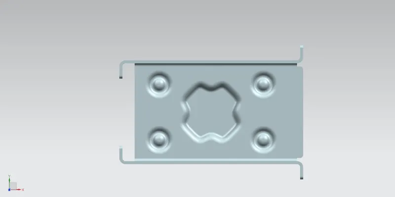
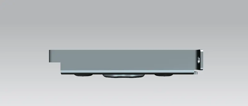
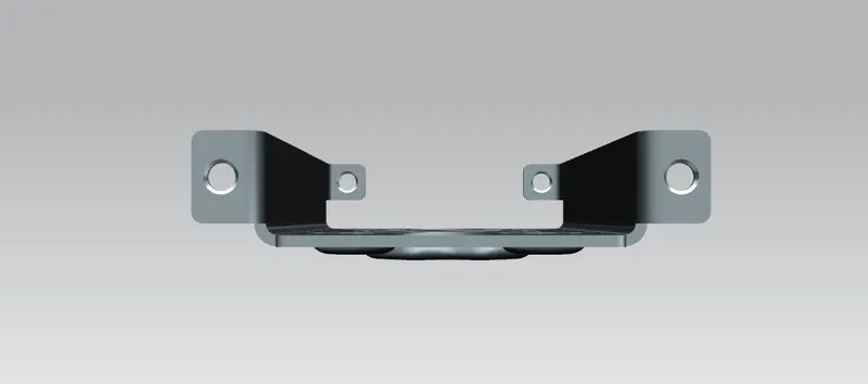
PART IMAGES :-
CONCLUSION:-
By this challenge i have learned how to use basic features like Tab,flange,break corner,dimple,unbend,rebend etc
Part file:-
https://drive.google.com/file/d/1xbhaTae0LrQWGUDaUqLG6hWM4aEWDCQZ/view?usp=sharing