ADAMS Car - Wheel and Ride Rate Optimization - Suspension Design
Find out the wheel rate of the suspension through simulation
Calculate the wheel rate of the suspension using the formulas discussed in class. Why is the number obtained in simulation different ?
The target wheel rate is 20 N/mm. Achieve this through two ways:
Modifying the spring
Modifying the hardpoints (change the spring motion ratio and state what it was before and after the change)
After you tune the suspension to achieve the wheel rate target, calculate the ride rate. Verify this using the simulation. They should be very close
The target ride rate is
- 19.5 N/mm
- Same as wheel rate
Achieve the ride rate targets without modifying the wheel rate (i.e without tuning the spring or hardpoints)
What needs to be done to make the wheel rate and ride rate the same? What do you understand from this?
Open the mdi_front_vehicle.asy and find out the spring motion ratio. Why is the motion ratio of the McPherson strut much higher than that of the double wishbone suspension?
Your Answers
The double-wishbone model is as follows :
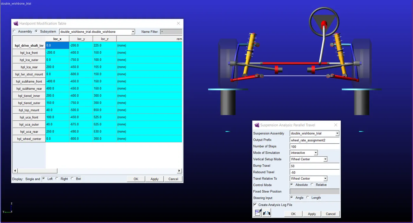
As the above figure depicts, the double wishbone geometry is simulated in a parallel travel analysis, for 100 steps, with a bump travel of 50mm and rebound travel of -50mm.
The wheel rate is analysed in the postprocessor and the plot of wheel rate versus the wheel travel is as follows :
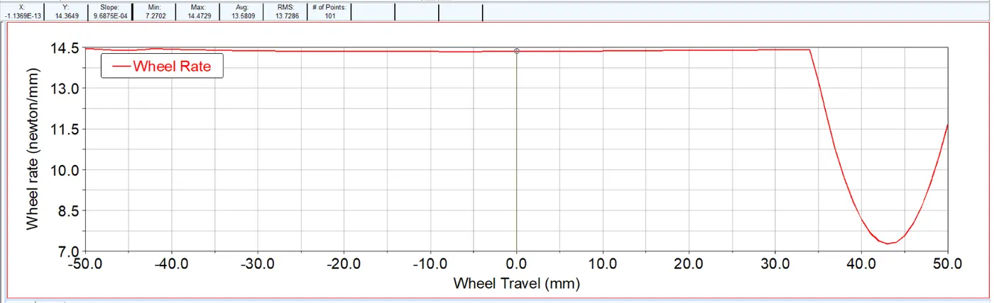
The wheel rate at ride height ( when wheel travel is zero) is 14.365 N/mm.
Wheel rate is vertical force acting on the tire per unit vertical displacement. The formula to calculate the wheel rate is given as below :
`K_w=K_s⋅MR^2`
Where `K_w` is the wheel rate, `K_s` is the spring rate and `MR` is the motion ratio.
The spring rate is calculated from the spring configuration files. The spring rate the spring force per unit displacement. The following depicts the plot between the spring force and displacement. The slope of the graph gives the spring rate. The spring is a bi-linear spring, hence only the initial slope is considered in this case.
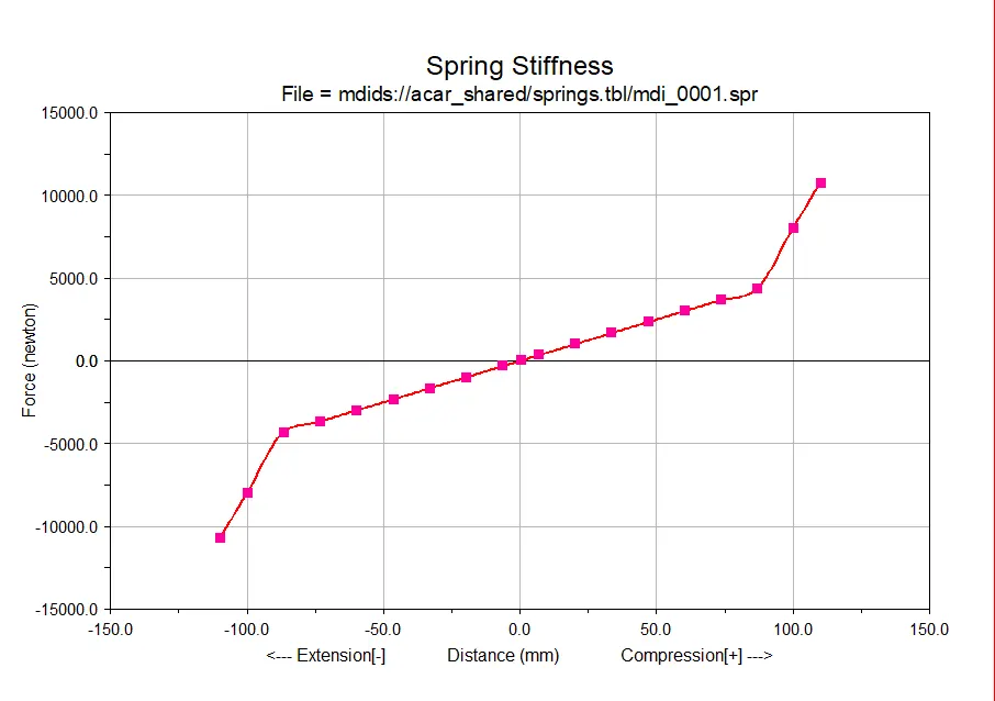
The spring rate is calculated to be 50N/mm. The motion ratio is the inverse of the mechanical advantage. It gives the information regarding how much the spring moves with respect to the movement of the wheels. The motion ratio is calculated as follows :
Motion ratio = `(175/375)⋅sin(78.69^o)=(175⋅0.9806)/375=0.4576.`
Based on this the wheel rates is calculated. Wheel rate = `50⋅(0.45762)=10.47N/(mm)`
| Parameter | ADAMS simulations | Hand calculations |
| Wheel rate (N/mm) | 14.365 | 10.4705 |
The difference in the because of the fact that the motion ratio is not constant throughout the suspension travel. The plot of the motion-ratio and wheel travel is not linear. The modified formula is used in the simulation and the formula is as follows :
`Kw=(K_s⋅MR^2)±F_s⋅((δMR)/(δWT))`
Where `F_s` is the spring force, `δMR` is the change in motion ratio and `δWT` is the change in wheel travel parameter. This ratio is simply the slope of the curve between the motion-ratio and wheel travel.
The target wheel rate is 20 N/mm. There are two ways in which the target wheel rate can be achieved. One is by changing the spring rate and the other alternative is to change the motion ratio, by tuning the hardpoints.
Changing spring rate : The higher spring rate has to be used at the same motion ratio geometry to attain the desired wheel rate of 20N/mm. By hand calculations, the spring rate has to be around 72N/mm. The springs having stiffness around this range is used and similar parallel travel analysis is performed. The resultant postprocessor graphs are as follows :
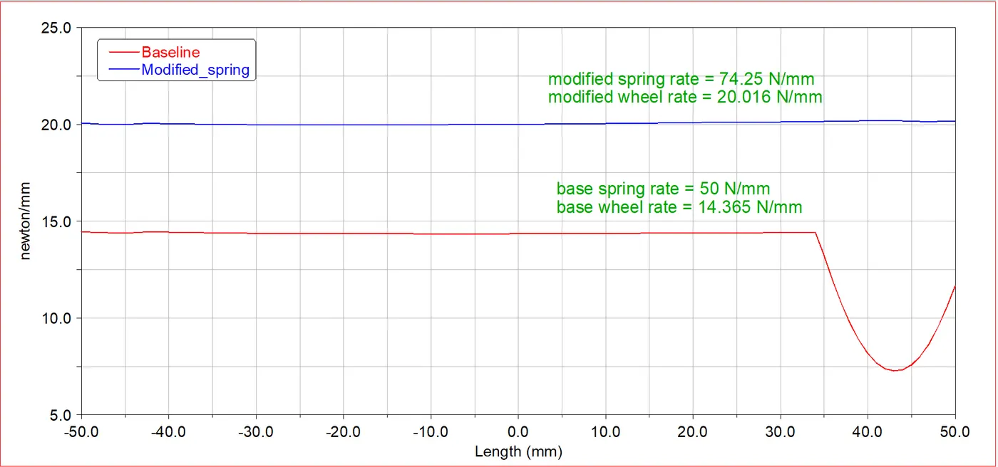
The base curve deviates beyond 35-36mm, because the spring used in the base system is a bi-linear spring, and hence the spring rate changes beyond that point. The new spring is modified to the spring rate of 74.25 N/mm. By tuning the spring to this stiffness, the wheel rate of 20N/mm is attained.
Change the hardpoint: The alterantive way to alter the wheel rate is to change the motion ratio. The motion ratio can be modified by varying the spring lower mount hardpoint. By doing this the mounting angle and the mounting distance from the wheel centre varies, thus the motion ratio will also change. Initially, the hand calculation is performed keeping the base spring rate to be same. The motion ratio required to achieve the required wheel rate has to be around 0.632. The lower control arm distance in this case is kept constant at 325mm, while the spring lower mount distance from the wheel centre alone is varied. The hardpoint mentioned is varied to obtain the wheel rate of 20 N/mm. The postprocessor plot is as follows:
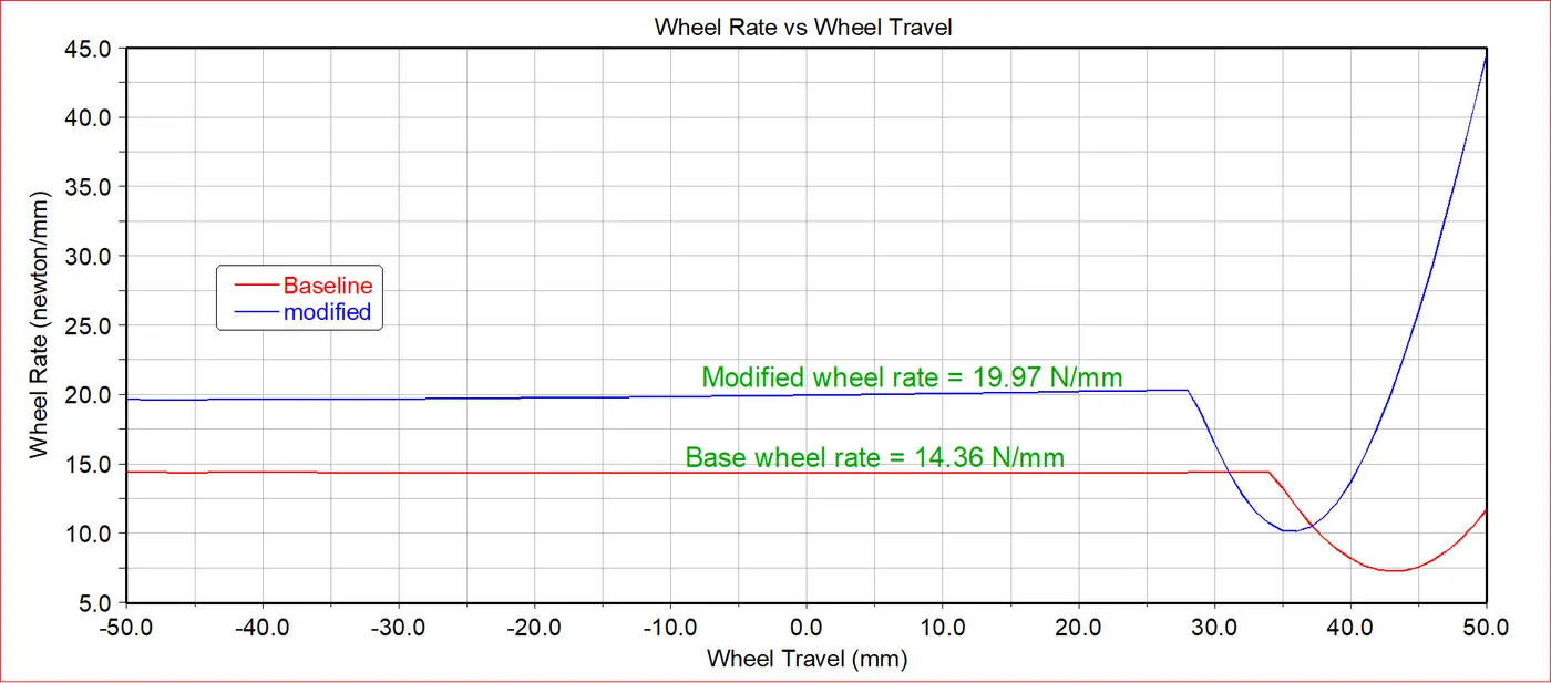
only the linear region is considered. The hardpoint of the strut lower mounting on the lower control arm was varyied from [0,-600,150] to [0,-636,150]. This changes the strut mounting distance and angle thereby the required motion ratio is attained. The wheel rate following the hardpoint change is 19.97 N/mm.
Ride rate :
The ride rate is the vertical force required to produce a unit vertical displacement at the tire-ground contact patch with respect to the chassis. The ride rate is mathematically the parallel combination of the tire stiffness and the wheel stiffness. The formula of the ride rate is as follows :
`1/K_r = 1/K_w+1/K_t ⇒ K_r = (K_w⋅K_t)/(K_w+K_t).`
The base ride rate curve before the wheel rate was modified and tuned is as follows :
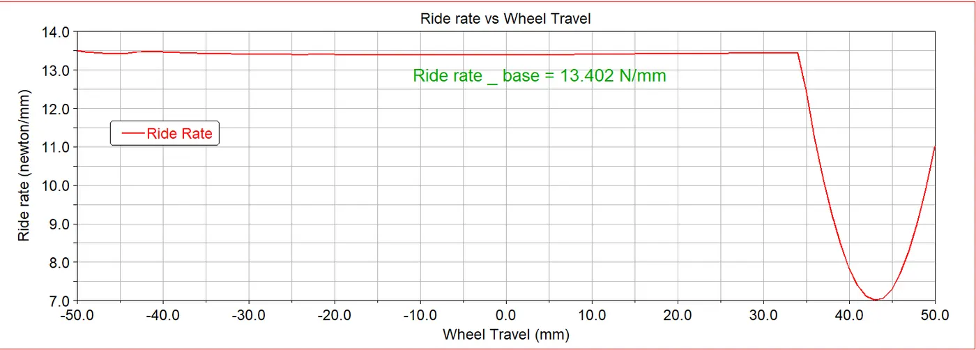
Based on the formula if calculated we get the following results :
The tire stiffness at the default state is 200N/mm.
Ride rate = `k_r=(20.016⋅200)/(200+20.016) =13.402 N/(mm)`
After the wheel rate was modified to attain the target value of 20N/mm, the ride rate is as follows :
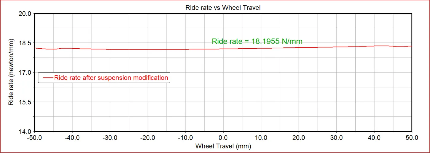
Based on hand calculation the ride rate =
`k_r = (20.016⋅200)/(200+20.016) =18.195N/(mm)`
The values are tabulated as follows :
| Parameter | Hand calculations | Based on results in ADAMS |
| Ride rate before suspension modification (N/mm) | 13.402 | 13.402 |
| Ride rate after suspension modification (N/mm) | 18.195 | 18.1955 |
The values based on the simulation and the hand calculation are same.
Next the vehicle ride rate has to be modified without modifying the wheel rate. This is possible only by varying the tire rate (or tire stiffness value). The vehicle ride rate target are as follows :
Target vehicle ride rate = 19.5N/mm.
The tire rate is modified to achieve a ride rate of 19.5N/mm while keeping the wheel rate at 20.016N/mm. The default tire stiffness value is 200N/mm. This value is tuned to attain the required ride rate.
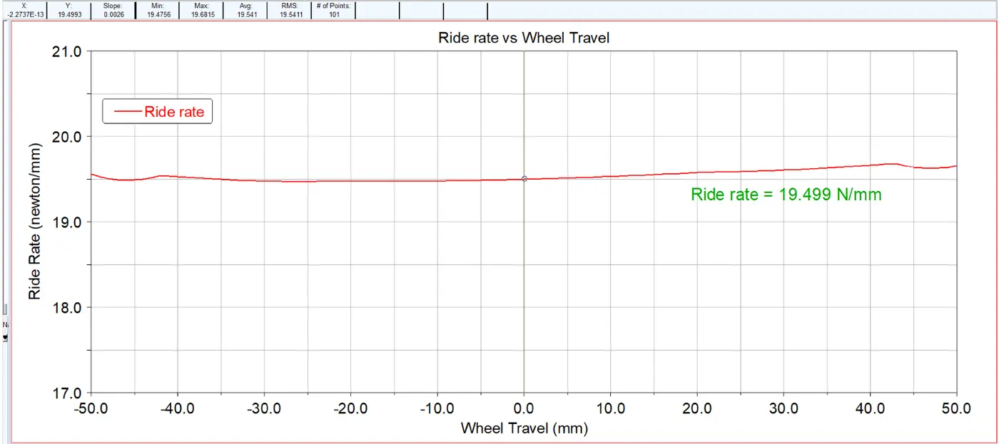
The tire rate was modified to 758 N/mm. Then the required ride rate of 19.499(~ 19.5) N/mm was attained.
Target vehicle ride rate = same as wheel rate = 20.016 N/mm.
Mathematically, if analysed for the ride rate and wheel rate to be same, the tire stiffness has to be infinite, the tire has to be completely rigid. Inotherwords, the tire rate has to be comparably very large to the wheel rate. Likewise the tire stiffness is set to very high value . By setting these parameters, a ride rate same as the wheel rate is obtained.
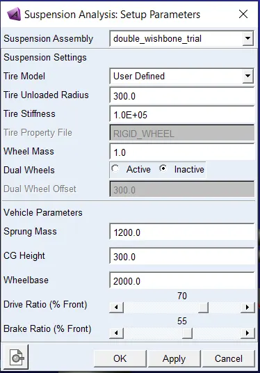
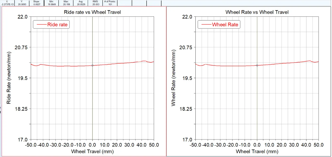
As seen in the above figure the tire stiffness to increased to a high value of 1.0E+05 N/mm. This gives the ride rate of 20.01N/mm while also maintaining the wheel rate to be 20.01N/mm. The graph from the postprocessor is as follows :
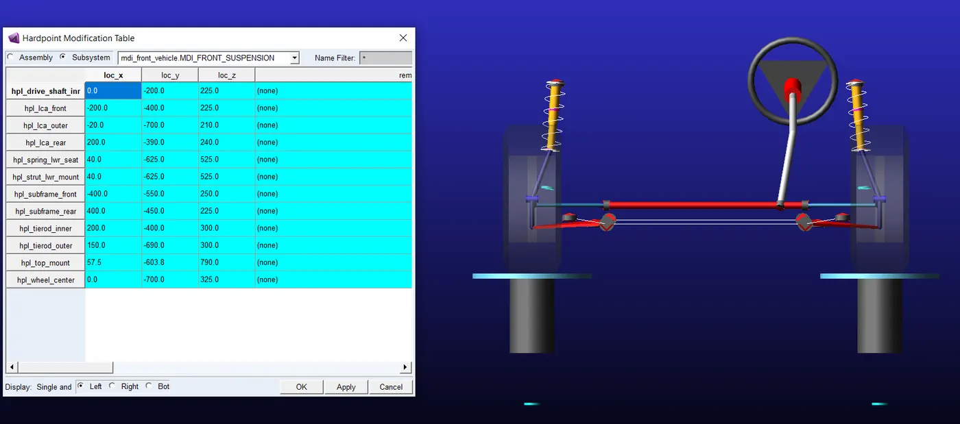
McPherson strut assembly
The assembly and the hardpoints of the McPherson strut is as follows :
The Mchperson strut usually has a higher motion ratio, because the angle at which the strut is mounted is also high, and the strut load path extended to more near the lower ball joint. This results is a much smaller distance of the strut lower mount and the wheel centre. So the motion ratio is thus much higher for the mchperson strut when compared to the double wishbone geometry.
Because the strut is mounted on the upright/ steering knuckle directly, packaging it easier, and the strut is more closer to the wheel centre. By doing this the kingpin lateral offset can be reduced. Therefore the value of BB increases. The strut has to be kept as vertical as possible in the McPherson type setup, to take up the maximum amount of shock, but due to packaging constraints, it cannot be kept at 90degrees, hence the least possible angle is given. This cause the θθ value to increase compared to the double wishbone. In other words the value of BB and θθ in the below image is higher for a McPherson strut.
Based on the coordinates the values of A and B are measured, and then the motion ratio is calculated using the formula:
motion ratio = `(253.4*sin(85.42))/305 = 0.828`.
The value of motion ratio is thus higher compared to that of the SLA type suspension.