ADAMS Car - Steering Geometry Optimization
Perform steering geometry optimization to achieve the following targets
Outside turn circle diameter – under 12.0 m
Ackermann at 20 deg inner steer angle – ~60%
These are subject to the following constraints
Max inner tire steer angle – 40 deg (for tire envelope/packaging reasons)
Max permissible rack travel – 85 mm.
Once this is done, perform the following :
Calculate the C-Factor of the system that is currently in the model (This is a bit tricky. Refer to the notes)
Find out the steering ratio on center
Tune the C-Factor to achieve an on-center steering ratio of 16.00
Plot steering ratio vs steering wheel angle (overlay the curves obtained before and after tuning the C-Factor)
Check for the following Baseline in the Template and then provide the proper changes.
Current C – Factor is 36 mm/rev, corresponding to a reduction ratio of 0.174 rad/mm. The steering ratio on-center is around 22
For the target steering ratio of 16, the C-Factor should be 60 mm/rev, corresponding to a reduction ratio of 0.10474
Solution.
The double wishbone geometry and the hardpoints is as follows :
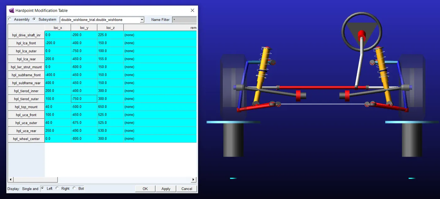
The steering geometry optimization has to be performed to achieve the given target by keeping the given constraints under check. The targets and constraints are as follows :
| Target Parameter | Value |
| Outer turn circle diameter at 20 degrees outer steer angle | < 12m |
| Ackermann percentage at 20 degrees inner steer angle | ~ 60% |
The constraints are as follows :
- The maximum permissible inner steer angle = 40 degrees.
- The maximum permissible rack travel = 85mm.
The suspension and steering geometric hardpoints have to be modified to achieve the targets. The initial value of these target parameters are first simulated and the post-processor graphs are given below.
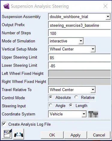
Outer turn circle diameters before optimization is 15.16 m.
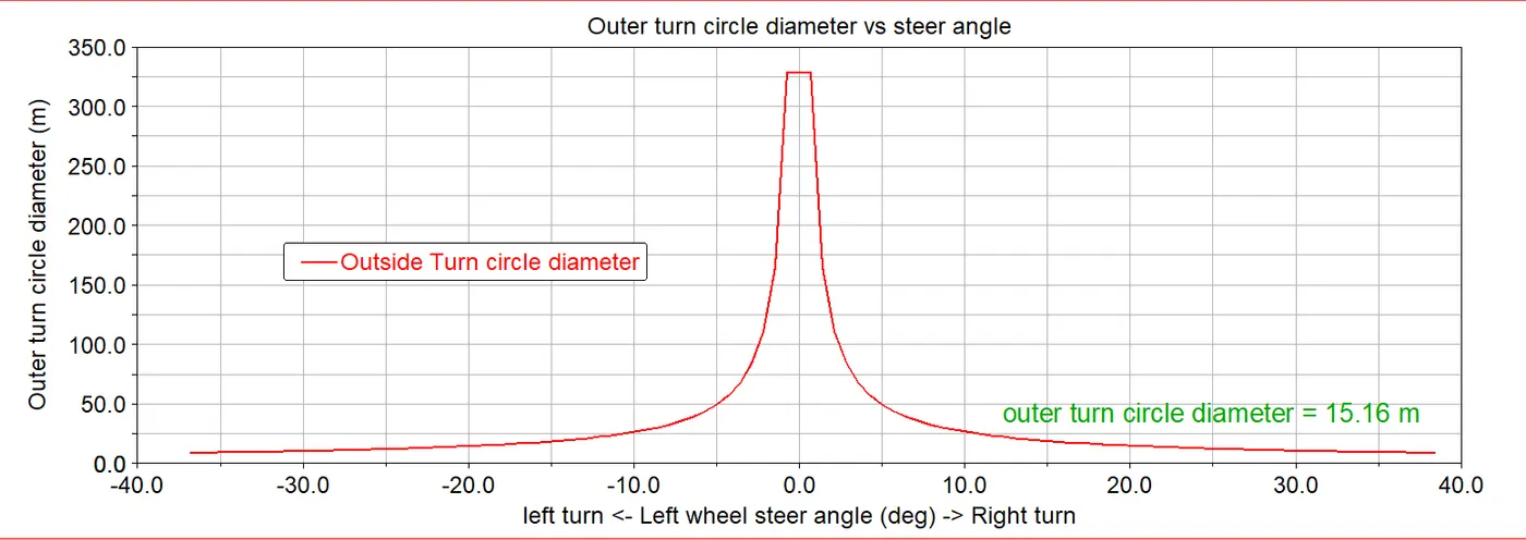
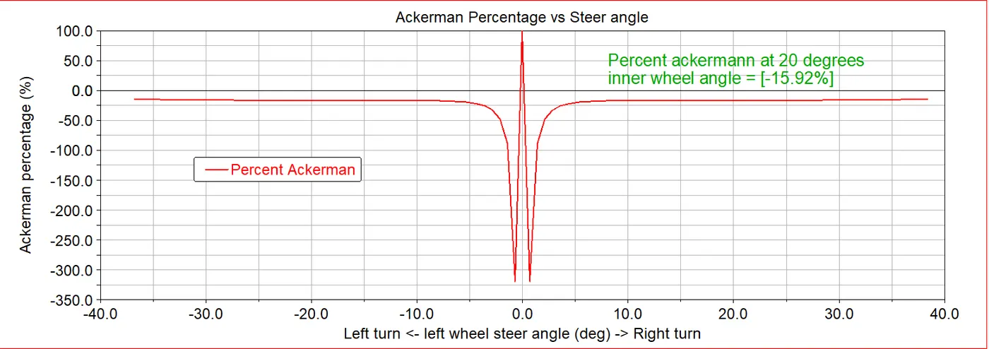
The ackermann percentage before optimization is -15.92%. The geometry is a reverse ackermann geometry. The hardpoints have to be tuned to get a ackermann geometry with an ackermann percentage of 60%. The initial value plot is given below.
The ackermann percentage is defined as the ratio between the wheelbase to that of the distance of the turn centre from the front steering axle axis. The formula for calculating the ackermann percentage is as follows :
`%ackerman = (Wheelbase)/(X−i ntersection)`
But in the ADAMS processor, the ackermann percentage is the ratio between the actual steer angle and the ideal steer angle. The formula involved in the calculation of the ackermann percentage using the steering angles are as follows:
`%ackerman n = (IT−OT)/(IA−OA)`
where,`IA=tan^(−1)((WB)/(A−KPC))` and `OA=tan^(−1)((WB)/(A+KPC))`
Major ways to change the % akermann are as follows :
- One major way to modify the ackermann percentage is to optimize the angle between the tie-rod and the steer arm to get the desired ackermann percentage. This can be modified by changing the tie-rod outer hardpoint.
- The other alternative way to change the ackermann percentage is to move the steering rack forwards or backwards.
- Another way is to modify the kingpin hardpoints. This is not a recommended change because it will change the other suspension parameters as well
The other parameter to be modified in the outer turn circle diameter. This formula for the outer turn circle diameter is as follows:
`TCD=2⋅[sqrt((A+KPC)^2+WB^2)+KPO+(T_w/2)]`
The turn circle diameter can be varied by modifying the wheelbase or trackwidth or the kingping offset. The other function that affects the turn circle diameter is the value of A which depends on the steer angles. In this setup, its difficult to change the wheelbase and trackwidth as it will affect several other parameters. The outer steer angle is fixed to a maximum of 40 degrees ( constriant parameter ). The kingpin offset and the outer steer angles are the only other parameters which can be modified. But modifying these will affect the ackermann percentage. As the ackermann percentage also depends on the outer steer angle and the kingpin offset and noticed in the above formulas of the ackermann percentage. As indicated in the plot above the outer turn circle radius is more than the target, it has to be reduced. But while reducing the turn circle diameter the ackermann percentage must also be kept under check, as to the fact that it doesnt deviate much from the 60% mark.
Optimization of the steering parameters
Initially, the tie-rod outer point Y-coordinate is varied to attain the required ackermann percentage. But at this hardpoint the turn circle diameter is above 12m, it is around 13m. Any other modification done to reduce the turn circle diameter will increase the ackermann percentage beyond 60 percentage mark.
The modification done is as follows:
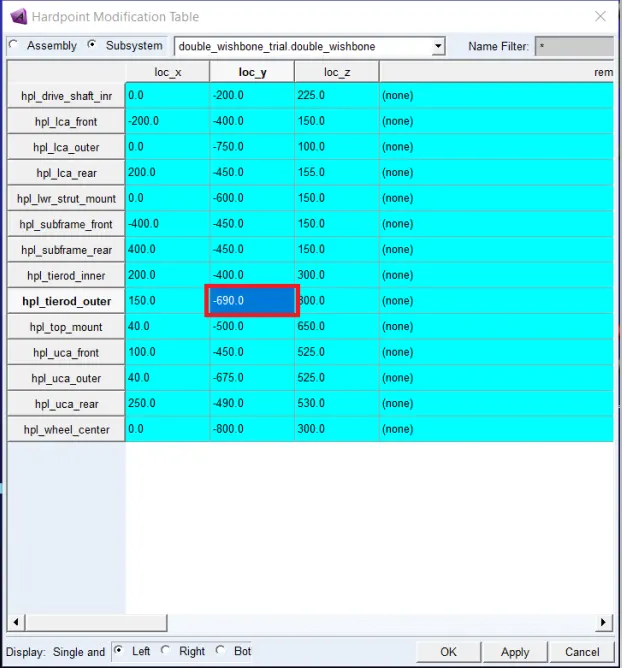
The parameters after the modification is as follows :
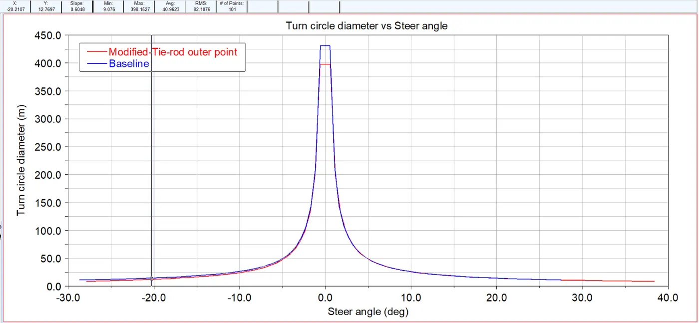
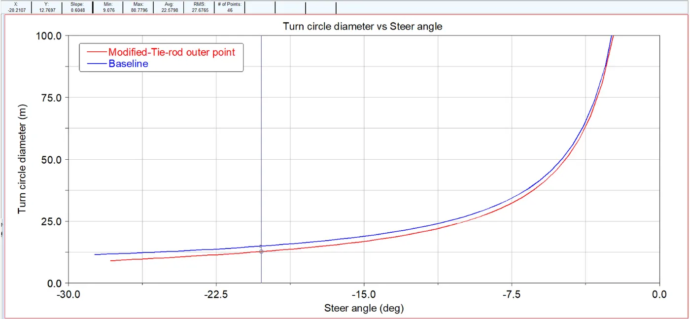
Magnifying the region of the plot under consideration, we can observe that the turn circle diameter has been reduced to 12.899m.
The other parameter is the ackermann percentage, the plot is as follows :
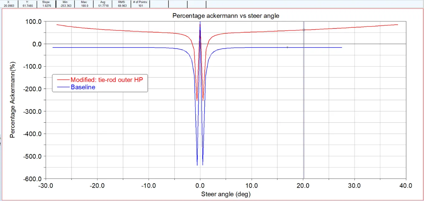
The percentage ackermann at 20 degrees for the inner wheel is simulated to be 61.65% for the respective hard point change.
- Turn circle radius = 12.89 m
- Ackermann percentage = 61.65 %
Any more modification in the hardpoints, to decrease the turn circle diameter causes an increase in the ackermann percentage. The two parameters have to be balanced. one of the parameters is set at the target value and the other parameter is optimized to be as close to the target. In this case, the ackermann percentage is set at ~60% (61.65%) and the turn circle diameter is optimized to be as close to 12m, but the attained value is 12.89m. Any other modification to reduce the turn circle diameter will increase the ackermann percentage.
The ackermann percentage when the turn circle diameter is below 12m is found to be 88%. This percentage is high.
Calculation of the C-factor for the current model :
C-factor is defined as the ratio between the rack travel in mm per one revolution of the pinion. The pinion is connected to the steering wheel, so in otherwords, the rack travel per one complete rotation (360deg) of the steering wheel is called as the c-factor. This parameter is a characteristic of the steering rack.
C-factor = rack travel (mm) / 360% of the pinion
For this the postprocessor plots is used. We keep the hardpoints the same, but simulate the same analysis with the steering angle as the input. The steering angle rotation required to produce the same inner and outer wheel angle is found out. For the steering rack travel of 65mm, currently the inner steer angle is 38.42 degrees and the outer wheel angle is 27.87 degrees. The input of wheel steering angle is given, and checked at what angle this angle of inner and outer wheel angle is obtained.
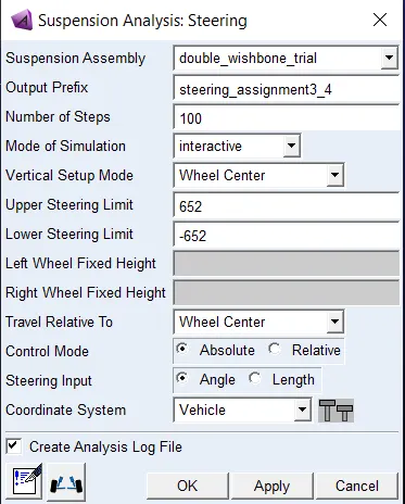
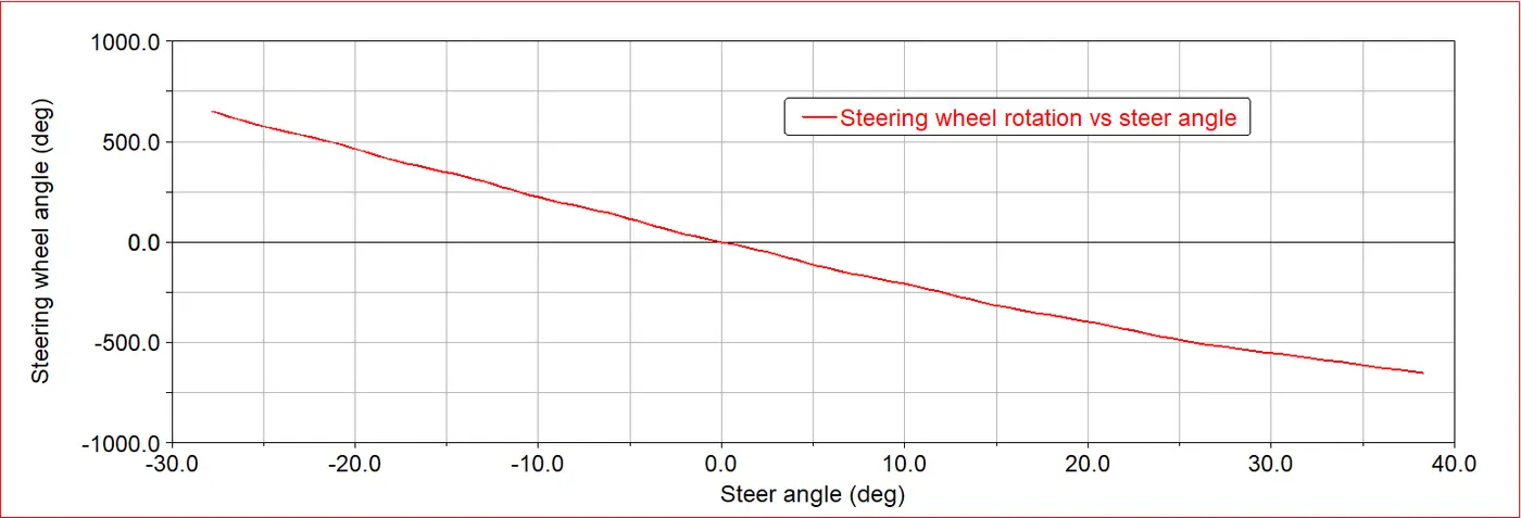
The steering angle is found to be 652 degrees. So, for this much pinion rotation, the rack travel is 65mm, whereas for 360 degrees ( one rotation), the rack travel is found to be :
rack travel = (65/652)*360 = 0.0997*360 = 35.89 ~ 36.
The C-factor is hence calculated to be 36mm/rev.
Find out the steering ratio on center
The steering ratio based on this c-factor and steering arm length is calculated using the following formula :
`SR=360/sin^(−1)((c−fac t o r)/(SA−l eng th))`
Where SR is the steering ratio and SA-length is the steering arm length.
c-factor is calculated to be 35.88, and the SA-length is calculated to be 154.03mm. Substituing these values, the steering ratio is :
`SR=360/sin^(−1)(35.89/154.03)=360/13.474=26.72`.
The steering ratio is 26.72.
Tune the C-Factor to achieve an on-center steering ratio of 16.00
The steering ratio changed by tuning the C-factor. The C-factor for a steering rack remains the same. In order to modify the C-factor, the steering rack pinion and rack gear designs have to be modified. An alternative way to tune the steering ratio is to alter the steering arm length. In this case, both the modification is done.
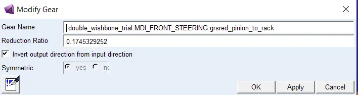
The following change is done in the value of the reduction ratio :
Initial value :
Modified value:
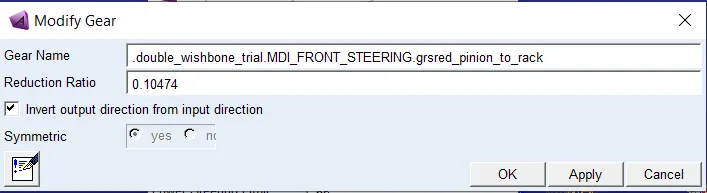
The reduction ratio is modified from 0.17453 to 0.1047. The corresponding steering wheel input given to obtain the same inner and outer wheel steer angle (In other words to obtain the same rack travel of 65mm) is 387 degrees. The following plot indicates that for the same steer angles the steer wheel angle has to be reduced to increase the c-factor.
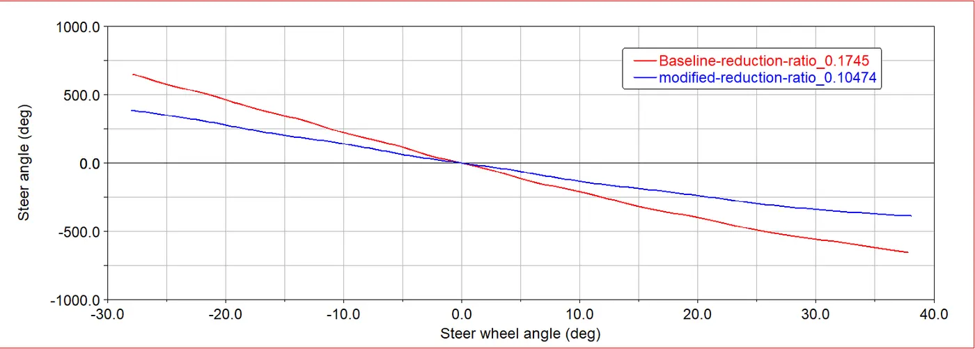
At the modified reduction ratio, the steer angle is 387 degrees, which produces the 65mm rack travel. The calculation of c-factor is as follows :
c-factor = rack travel / one rotation of the pinion = (360/387)*65 = 60.46 ~ 60 mm/rev.
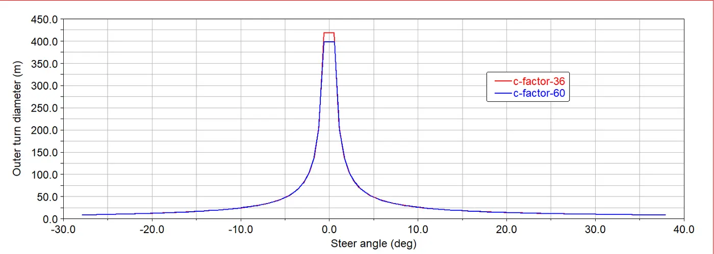
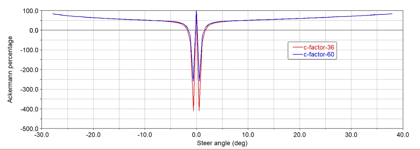
The required steering ratio is 16. To obtain this for the c-factor of 60mm/rev , the steering arm length has to be modified. The hardppoints are tuned to obtain the same outer turn diameter of below 13m and percentage ackermann of 60%. A back calculation can be performed to determine the steering arm length and then modify the tie-rod outer point accordingly.
`16 = (360/(sin^(−1)(60.4/(sa−l eng th)))) ⇒ 60.4/(sa−l eng th) = sin(360/16) ⇒ sa−l eng th = 60.4/sin22.5=157.83`
To obtain the steering length as calculated above , the X-coordinate of the tie-rod outer point has to be modified from 150 to 156. Then the Y-coordinate is tuned to obtain the required ackermann percentage and outer turn diameter. The following table indicates the modification in the hardpoints.
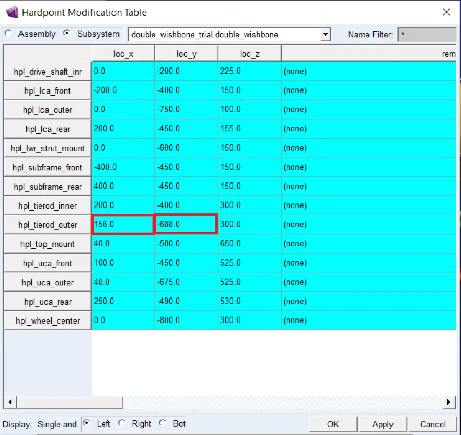
The following is the postprocessor plot of the outer turn diameter and percentage ackermann is given below, the initial setup and the final setup are overlayed.
The steering ratio is calculated as follows :
`SR=360/sin^(−1)(60.4/157.8)=15.99~16`
Plot steering ratio vs steering wheel angle
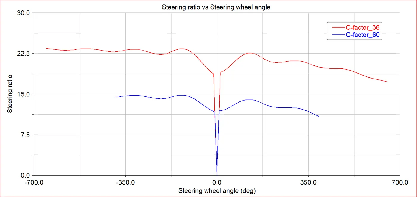
The y-axis expression of steering ratio is considered to be the ratio between the steering wheel angle to that of the steer angle of the wheels. It is plotted against the steering wheel angle.